Beacon Power Supply Installation Instructions
2.8.2012
52-296 Rev B05
Page 11 of 27
AlarmSaf
65A Industrial Way, Wilmington, MA 01887 978 658 6717 www.alarmsaf.com
3.5 ABC Voltage Selection
The output voltage of the BNx000 must be carried through the Accessory Board Connector (P2)
when using the BN x000 power supply with Beacon Accessory Modules that connect to P2 using
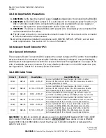
ABC cables. The Buss Select Fuse (See Figure 3.5.1.1) determines if the voltage is available on
the Accessory Board Connector (P2).
Figure 3.5.1.1
3.5.1 Adjusting the Buss Select Fuse
The Buss Select Fuse is factory set for proper operation. The Fuse setting options are:
SETTING/POSITION
DESCRIPTION
B1 – DOWN
Makes the power supply voltage available on the Accessory Board Connector (P2).
This is the required setting when connecting a Beacon Accessory Module.
B2 - UP
Removes voltage from the Accessory Board Connector (P2).
Because older BNx000 boards (PCB#: 38-118 REV A02 or earlier) do not have a Buss Select
Fuse, always check the position of this fuse setting when installing a new BNx000 Board (PCB #
38-118 REV A03A or later) into an existing system.
3.6 Output Terminals
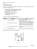
The BNx000 has three sets of output terminals:
The DC1 output provides constant power, regardless of the state of the FAI input
The DC2 output provides power which DROPS upon activation of the FAI input
The DC3 output provides power ONLY upon activation of the FAI input
All three sets of output terminals on the BNx000 provide the same output voltage, 12VDC or
24VDC, as selected by the voltage select switch (S1). See Section 5.1 for more information.
D13
F4
TB2
TB1
-BAT+
-DC3+
-DC2+
-DC1+
DC2
DC1
DC3
Figure 3.6.1
CAUTION: Observe polarity of the BNx000 output terminals as indicated on the board with
respect to the load or damage to the load may occur.


