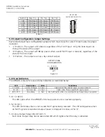
Table 5.2
OFF (Open)
ON (Closed)
OFF (Open)
6 (P)
ON (Closed)
ON (Closed)
OFF (Open)
5 (PI)
OFF (Open)
ON (Closed)
OFF (Open)
4 (P)
OFF (Open)
OFF (Open)
ON (Closed)
3 (N)
ON (Closed)
OFF (Open)
ON (Closed)
2 (NI)
OFF (Open)
OFF (Open)
ON (Closed)
1 (N)
Ext. Trip
Pos. Trip
Neg. Trip
Switch #
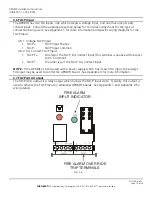
5.3 Output Configuration Jumper Settings
Each Zone Output has a configuration jumper which must be set for one of three modes for proper
operation.
y
‘C’ Position - The output is ‘
C
’onstant, regardless of the FACP input. Only the Zone Input can
change the state of the output.
y
‘D’ Position - The output will ‘
D
’rop power when a valid FACP input is received, regardless of the
state of the Zone Input.
y
‘X’ Position - The output is set as a dry contact output.
Figure 5.3
X
D
C
JP1
S1
OUTPUT ZONE
CONFIGURATION
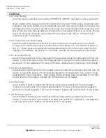
5.4 Visual Indicators
The APD8(F) contains ten visual status indicators as described below.
Each LED lights when its associated Zone Output relay is powered.
Red
Zone Relay
(D10-D17)
Lights when there is
no
FACP input present
Green
Fire Override
FO (D1)
Lights when the internal power source is present
Green
Control Voltage
CV (D33)
Conditions
Color
Description
LED
5.4.1 CV (D33)
This LED lights when the APD8(F)’s internal power source is operating properly.
5.3.2 FO (D1)
This LED illuminates there is not a valid FACP signal being received. This LED extinguishes when
an FACP signal is received and output power is dropped to zones set for ‘D’.
5.3.3 Zone Output Relay LEDs (D10-D17)
Each Zone Output relay has an associated LED which lights when the relay is activated.
APD8(F) Installation Instructions
10/9/2007, 12:19:29 PM
Page 15 of 24
AlarmSaf
65A Industrial Way, Wilmington, MA 01887 978 658 6717 www.alarmsaf.com
P
PI
P
N
NI
N
+IN 1-
INPUT ZONE
CONFIGURATION SWITCH
52-254 Rev B01


