background image

Table of Contents

Section

Page

I.  Warnings and Notices

2

1  Introduction

4

2  Applicable Standards / Documents

5

3  System Overview

6

3.1 Electrical Ratings and Specifications

6

3.2 Connector Descriptions and Electrical Ratings

7

3.3 Control Power and Lock Power Input Connections

8

3.4 Zone Inputs

9

3.5 Zone Outputs

9

3.6 FACP Input

10

3.7 FACP AUX Output

10

3.8 Fusing

11

4  Installation

12

4.1 Mounting

12

4.2 Wiring

13

5  Operating the APD8(F)

14

5.1 Power Separation Jumper Settings

14

5.2 Zone Input Configuration Switch Settings

14

5.3 Output Configuration Jumper Settings

15

5.4 Visual Indicators

15

5.5 Troubleshooting

16

6  Specifications

17

6.1 Electrical Specifications

17

6.2 Temperature Specifications

17

6.3 Mechanical Specifications

17

Appendix A

Configuring the Zone Inputs For Any Application

18

Appendix B

Using The Zone Outputs

20

Appendix C

Using the FACP Input and FACP AUX Output Terminals

21

Appendix D

Sample Applications

22

APD8(F) Installation Instructions
10/9/2007, 12:19:29 PM

Page 3 of 24

AlarmSaf

 65A Industrial Way, Wilmington, MA 01887 978 658 6717 www.alarmsaf.com

52-254 Rev B01

Содержание APD8-BD

Страница 1: ...N4 003 APD8F UL 10009 BN4 003 APD8 UL 10007 BN4 004 APD8F UL 10010 BN4 004 APD8 UL 10008 BN6 003 APD8F UL 10021 BN6 003 APD8 UL 10019 BN6 004 APD8F UL 10022 BN6 004 APD8 UL 10020 Model Numbers Order N...

Страница 2: ...Installation Instructions 2 8 2012 52 296 Rev B05 Page 1 of 27 AlarmSaf 65A Industrial Way Wilmington MA 01887 978 658 6717 www alarmsaf com Beacon Power Supply Operating and Installation Instruction...

Страница 3: ...k Installation and service should be made by qualified service personnel and should conform to all local codes III WARNING Read the instruction manual to avoid personal injury or property damage IV NO...

Страница 4: ...onnector Illustration 8 3 3 AC Input Connection 9 10 3 4 Accessory Board Connectors ABC 10 3 5 ABC Buss Voltage Selection 10 11 3 6 Output Terminals 11 3 7 FAI Input Terminals 12 3 8 Fault Reporting T...

Страница 5: ...12V devices such as mag locks Expandable with accessory boards via the ABC connector All units can charge up to 38AH of battery while supplying full rated load Full fault detection including battery p...

Страница 6: ...cessory Board Installation Manual 52 352 MB8 F Accessory Board Installation Manual 52 254 APD8 F Accessory Board Installation Manual 52 326 PD8 F Accessory Board Installation Manual 52 350 SPS4 Access...

Страница 7: ...t Power BN4000 125W maximum BN6000 190W maximum BN8000 250W maximum BN10000 330W maximum Output 12 or 24VDC nominal at BN4000 4A 24V out or 8A 12V out 110W BN6000 6A 24V out or 12A 12V out 165W BN8000...

Страница 8: ...output current of supply See Section 3 1 for ratings Output deactivates upon FAI Activation DC2 DC2 Common Output TB2 DC3 and BAT Outputs DC3 DC3 Positive Output Full output current of supply See Sec...

Страница 9: ...r Supply Installation Instructions 2 8 2012 52 296 Rev B05 Page 8 of 27 AlarmSaf 65A Industrial Way Wilmington MA 01887 978 658 6717 www alarmsaf com 3 2 1 BNx000 Terminal and Connector Illustration F...

Страница 10: ...3 1 Configuring VAC Input All BNx000 power supplies are factory set for 120 VAC input 102 138VAC at 50 or 60Hz To verify 120 VAC input setting Locate the VAC SELECT jumper J5 Verify that J5 is in the...

Страница 11: ...of available accessory modules For more detailed information on the ABC expansion port see Appendix B About the Accessory Board Connector 3 4 2 ABC Cable Types Order Model Description Used With Notes...

Страница 12: ...onnecting a Beacon Accessory Module B2 UP Removes voltage from the Accessory Board Connector P2 Because older BNx000 boards PCB 38 118 REV A02 or earlier do not have a Buss Select Fuse always check th...

Страница 13: ...inals on the BNx000 FAI input Terminal Description Use V Auxiliary Voltage Output An internal voltage source for use with dry contacts or open collectors L Positive FAI Activation Terminals These term...

Страница 14: ...5 AC FLT Normally Closed NC 6 AC FLT Common COM JP1 K3 NC NC COM COM NO NO SYS FLT AC FLT SYS TBL BPD D Figure 3 8 1 Fault Condition SYS FLT Relay Output AC FLT Relay Output Normal Condition No Fault...

Страница 15: ...em for the mounting surface CAUTION Remove all power from the system before installation Cabinet Mounting 1 Mark and pre drill two holes for the top keyhole mounting screws 2 Install two fasteners in...

Страница 16: ...not be routed across the circuit boards 4 2 2 AC Input Connection should be made via wire nut AC mains wiring should be no smaller than 14 AWG See Section 3 3 for details 4 2 3 ABC Connector See secti...

Страница 17: ...d is labeled with the connections and polarity See also section 3 2 Replace the terminal block on the header 4 2 7 Fault Relay Wiring Locate the Fault Relay Output terminal block TB4 and remove the te...

Страница 18: ...8000 10000 Figure 5 1 1 5 2 Jumper Settings For proper operation the jumpers on the BNx000 should be set appropriately All jumpers should be verified or set before powering the unit Jumper Descriptio...

Страница 19: ...n visual status indicators LED Description Color Conditions AC PWR D20 AC Power Green Lights when AC Power Present ACF D50 AC Fault Yellow Lights on low missing AC Power SYS TBL D33 System Trouble Yel...

Страница 20: ...g battery If Battery Presence is enabled 5 3 4 REV BAT D27 This LED lights when a battery set is connected to the BNx000 in a reverse polarity This LED will be accompanied by the SYS TBL LED and a blo...

Страница 21: ...per connection of the ABC cable s Bad Incorrect or Missing Battery Set Verify that a good battery set of the proper voltage is connected to the BNx000 Internal problem with BNx000 Contact AlarmSaf The...

Страница 22: ...ominal or 195 5 264 5 240VAC Nominal 50 60Hz 6 1 2 Input Power Model dependent See Sec 3 1 6 1 3 Output Voltage 12 or 24VDC Nominal 6 1 4 Output Current Model dependent See Sec 3 1 6 2 Temperature Spe...

Страница 23: ...urce a Normally closed b Normally open 2 Power from external voltage source a Switched positive b Switched negative 3 Open collector connection a Internal voltage source b External voltage 4 Direct to...

Страница 24: ...R OPEN COLLECTOR JP3 TB3 E D FAI BAT REV L L V V FAI INPUT V L L V EXTERNALPOWER EXTERNALPOWER OPEN COLLECTOR Internal source External source NAC connection JP3 TB3 E D FAI BAT REV L L V V FAI INPUT V...

Страница 25: ...us Products can be daisy chained together maintaining voltage fault FAI and DC common continuity throughout the chain NOTE There are 6 pin and 8 pin versions of the ABC The 6 pin version carries ONLY...

Страница 26: ...connected to each voltage buss before powering the system Fault Status Buss The fault status buss carries the DC Fault status between accessory boards and power supplies Any product with fault detect...

Страница 27: ...ctivation of any FAI input source will only activate accessory boards or power supplies up to the split Products after the split require their own FAI input source Note Not all accessory boards have F...

Страница 28: ...arm Interface Input present on some AlarmSaf products allowing control of output s in the system Typically used for dropping power to mag locks on egress doors during a fire alarm condition but can al...

Страница 29: ...SDH 7D Siemens 17 31 24 Door Holder SDH 6D Siemens 17 31 24 Door Holder SDH 5D Siemens 17 31 24 Door Holder SDH 4D Siemens 17 31 24 Door Holder SDH 3D Siemens 17 31 24 Door Holder SDH 2D Siemens 20 29...

Страница 30: ...NO C NC COM COM NC C NO NO C NC COM COM NC C NO OUT 2 OUT 3 OUT 4 OUT 5 OUT 6 OUT 7 OUT 8 IN 1 IN 2 IN 3 IN 4 IN 5 IN 6 IN 7 IN 8 SET S1 THRU S8 FOR EITHER POSITIVE NEGATIVE OR APD8 NO C NC FACP AUX...

Страница 31: ...es or other personnel working about the premesis by falling objects by building vibration and by similar causes y NOTICE This equipment is not intended for use within the patient care areas of a Healt...

Страница 32: ...r Separation Jumper Settings 14 5 2 Zone Input Configuration Switch Settings 14 5 3 Output Configuration Jumper Settings 15 5 4 Visual Indicators 15 5 5 Troubleshooting 16 6 Specifications 17 6 1 Elec...

Страница 33: ...em isolation provided by the APD8 F make this unit a universal toolbox for access control applications y Eight outputs each individually programmable for fail safe fail secure form C dry contact conti...

Страница 34: ...stems US Standards UL 294 Access Control System Units Canadian Standards CAN CSA C22 2 No 107 1 01 General Use Power Supplies Other Applicable Local and State Building Codes Requirements of the Local...

Страница 35: ...power source whichever is less Total Output Current 0 4A 12VDC 0 2A 24VDC maximum control current 8A maximum output current Input Power 10 30V AC or DC Input Voltage Product Use When installed in acc...

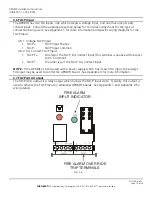
Страница 36: ...ontrol Power Positive Input CTRL TB7 Power Inputs and FACP AUX Output Rating Description Terminal Connector Figure 3 2 1 ISOLATED TRIP FO CV L0CK CTRL X D C C D X X D C C D X X D C C D X X D C X D C P...

Страница 37: ...2 are removed the Control Power input or Zone Inputs have NO connection to the Lock Power input or the Zone Outputs 3 3 2 Lock Power Input If J1 and J2 are removed this input provides power to the zon...

Страница 38: ...re voltage output Jumpers JP1 through JP8 select the type of output for each zone see Section 5 1 for jumper information See Appendix B for more information on the Zone Outputs 3 5 1 If the Zone Outpu...

Страница 39: ...C Common y FACP T The other leg of the FACP Dry Contact Input NOTE If the APD8 F is being used with a power supply which has its own FAI Input the supply s FAI input may be used to control the APD8 F...

Страница 40: ...C COM OUT 1 COM NC C NO NO C NC COM COM NC C NO NO C NC COM COM NC C NO NO C NC COM FACP NO C NC COM COM NC C NO NO C NC COM COM NC C NO NO C NC COM COM NC C NO NO C NC COM COM NC C NO OUT 2 OUT 3 OUT...

Страница 41: ...g wall leaving screwheads protruding approximately inch 3 Using the two upper keyholes mount the cabinet over the two screws 4 Mark the two lower holes remove the cabinet and drill the lower mounting...

Страница 42: ...nd remove the terminal block from the header Connect the input in the manner appropriate for the type of input signal being applied See section 3 4 and Appendix A for more information Replace the term...

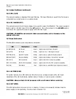
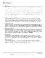
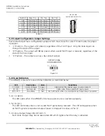
Страница 43: ...itional input types Note Only switches 1 through 6 are used for each input switches 7 8 are unused Note The factory configuration of these switches Negative Trip Mode should work for most applications...

Страница 44: ...tors The APD8 F contains ten visual status indicators as described below Each LED lights when its associated Zone Output relay is powered Red Zone Relay D10 D17 Lights when there is no FACP input pres...

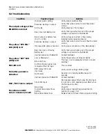
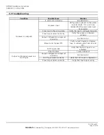
Страница 45: ...TC Blown Fuse Tripped PTC See Section 5 3 Output Configuration Jumper set incorrectly Verify the output is configured properly Zone Output wired incorrectly Verify the input is configured properly Zon...

Страница 46: ...C D X X D C C D X X D C C D X X D C X D C P PI P N NI N P PI P N NI N N NI N P PI P P PI P N NI N N NI N P PI P P PI P N NI N N NI N P PI P P P N NI N NO C NC COM NO C NC COM OUT 1 COM NC C NO NO C NC...

Страница 47: ...lay coil This is the most common configuration y NC Dry Contact Positive This configuration holds the zone output relay active The zone output relay deactivates when the NC contact opens The NC contac...

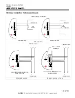
Страница 48: ...RNAL 12VDC P PI P N NI N IN 1 IN 1 IN 1 IN 1 P PI P N NI N EXTERNAL 12VDC Isolated Voltage Trip Negative Trip Positive Trip The trip source MUST be common grounded to the APD8 F s control power source...

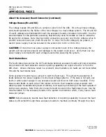
Страница 49: ...put y Voltage Output Constant C When the zone output configuration jumper is set in the C position the zone output will supply the voltage applied to the Lock Power Input Internally the Lock Input vol...

Страница 50: ...he open collector output will activate the FACP input Closure of the NO contact will activate the FACP input FACP T T T T SWITCHED VDC VDC COM FACP T T T T VDC FACP T T T T Isolated Voltage Open Colle...

Страница 51: ...con Power Supply s FAI action Any acceptable method of FAI connection can be used on the Beacon power supply Consult the Beacon Power Supply s installation manual for acceptable connection methods Act...

Страница 52: ...valid target Zone 1 provides constant power to the egress PIR through the C terminal The Zone Input is set for NC Dry Contact Negative See Appendix A and the Zone Output Configuration jumper is set f...

Страница 53: ...s its FACP AUX output These contacts then activate the FACP dry contact input of the bottom APD8 F Any valid FACP Input activation method can be used on the top APD8 F See Appendix C for more informat...

Отзывы: