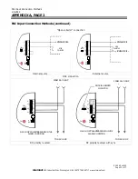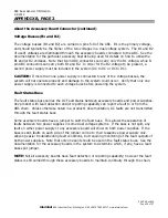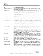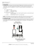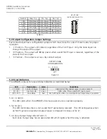
3.2 APD8(F) Connector Descriptions and Electrical Ratings
Zone x Output Power Common
OUT x COM
Zone x Output Normally Closed
OUT x NC
Zone x Output Relay Common
OUT x C
Output voltage determined by Lock Input Voltage
APD8 - 1.6A per zone maximum
APD8F - 3.0A per zone maximum
Zone x Output Normally Open
OUT x NO
TB1, TB2, TB3, & TB4 - Zone Outputs
Zone x Common Input
IN x -
12VDC Nominal @ 0.03A
Zone x Positive Input
IN x +
TB5 & TB6 - Zone Inputs
FAI Dry Contact Input Common
FACP T-
0.01A @ 12VDC Nominal
FAI Dry Contact Input Positive
FACP T+
FAI Voltage Input Common
FACP -
9VDC-30VDC - 0.01A @ 24VDC
FAI Voltage Input Positive
FACP +
TB8 - FACP Input
FACP Relay Output - Normally Closed
FACP AUX NC
FACP Relay Output - Common
FACP AUX C
1A @ 24VDC Maximum
FACP Relay Output - Normally Open
FACP AUX NO
Lock Power Common Input
LOCK-
10V-30V AC or DC - 8A Maximum - depending on output current
and voltage rating of power source
Lock Power Positive Input
LOCK+
Control Power Common Input
CTRL-
10V-30V AC or DC - 0.4A at 12VDC, 0.2A at 24VDC Maximum
Control Power Positive Input
CTRL+
TB7 - Power Inputs and FACP AUX Output
Rating
Description
Terminal / Connector
Figure 3.2.1
ISOLATED TRIP
FO
CV
L
0
CK
CT
RL
X
D
C
C D X
X
D
C
C D X
X
D
C
C D X
X
D
C
X
D
C
P
PI
P
N
NI
N
P
PI
P
N
NI
N
N
NI
N
P
PI
P
P
PI
P
N
NI
N
N
NI
N
P
PI
P
P
PI
P
N
NI
N
N
NI
N
P
PI
P
P
P
N
NI
N
NO
C
NC
COM
NO
C
NC COM
OUT 1
COM
NC
C
NO
NO
C
NC
COM
COM
NC
C
NO
NO
C
NC
COM
COM
NC
C
NO
NO
C
NC
COM
FACP
NO
C
NC
COM
COM
NC
C
NO
NO
C
NC COM
COM
NC
C
NO
NO
C
NC COM
COM
NC
C
NO
NO
C
NC
COM
COM
NC
C
NO
OUT 2
OUT 3
OUT 4
OUT 5
OUT 6
OUT 7
OUT 8
+IN 1- +IN 2- +IN 3- +IN 4-
+IN 5- +IN 6- +IN 7- +IN 8-
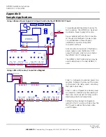
SET S1 THRU S8
FOR EITHER POSITIVE,
NEGATIVE, OR
APD8
NO
C
NC
FA
C
P
A
U
X
NC
C
NO
L
0
CK
CT
RL
PO
W
E
R
+IN 1- +IN 2- +IN 3- +IN 4-
+IN 5- +IN 6- +IN 7- +IN 8-
T+
T-
A
lar
m
S
af
W
ilm
ingt
on
, M
A
T+
T-
REPLACE FUSE ONLY WITH
FUSE OF SAME TYPE AND RATING
J2
J1
JP8
JP7
JP6
JP5
JP3
JP2
JP1
JP4
F1
F2
F3
F4
F5
F6
F7
F8
S1
S2
S3
S4
S5
S7
S8
TB
6
+
+
+
-
-
-
+
+
-
-
Note -
Wire should be sized appropriately for voltage drop and current carrying capability. All
terminals are labelled for polarity where appropriate.
APD8(F) Installation Instructions
10/9/2007, 12:19:29 PM
Page 7 of 24
AlarmSaf
65A Industrial Way, Wilmington, MA 01887 978 658 6717 www.alarmsaf.com
52-254 Rev B01


