


OG-UDC 3G-SDI Up, Down, Cross-Converter v1.0 16 www.aja.com
Chapter 2 – Operation
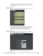
Default Operational Settings
The OG-UDC converter ships from the factory with the following configuration:
• Local (DIP switch) control (DashBoard shows status only).
• 1080i59.94 output with NTSC related inputs, or 1080i50 output with PAL
related inputs.
If these settings apply to your requirements, you can simply connect the video
and audio input and output signal cables.
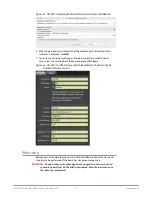
For other applications, you can configure the card using its DIP switch settings, or
by setting Remote (DIP switch) control and using the DashBoard Control System
and a PC or Mac networked to an openGear frame.
Using DIP Switches to Control the OG-UDC
The OG-UDC has two sets of DIP switches. The first set is used for general
configuration. The second set is used only for Reference selection. See
Figure 3 on
page 6
.
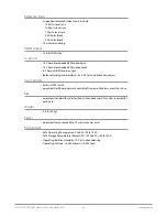
General Configuration DIP Switches
The General DIP Switch module is located on the left side of the card.
Figure 12. General Configuration DIP Switches
1
CONTROL
LOCAL
REMOTE
2
SD/HD
HD
SD
3
1080/720
1080
720
4
FMT0
0
1
5
FMT1
0
1
6
3:2
OFF
ON
7
SIDEB
UP
FULL
8
LTRBX
DN
FULL
The default DIP switch positions are all in the left position. The default settings
result in an output of 1080i59.94 with NTSC related inputs and 1080i50 with PAL
related inputs.
For 1080p 23.98/1080PsF 23.98 inputs, the input can be converted to 720p 23.98,
1080p 23.98, 1080i 59.94, or 1080p 59.94. The latter two would use the 3:2 DIP
switch to add 3:2 pulldown.
The compliance label, found on the card next to the DIP switches, lists the DIP
switch settings.
NOTE: HDMI monitors may not support all frame rates or "PsF" formats.
NOTE: The HDMI output does not support "PsF" formats. When the Video Output Format
is configured for PsF, the signal on the HDMI output is converted to interlace.
NOTE: OG-UDC converts 3G-A formats only. It does not accept 3G-B input or produce
3G-B output.