1
29
FS1 Installation and Operation Manual — GPI Connections
GPI Connections
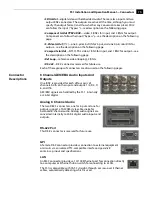
GPI Connector Pinout
The GPI inputs and outputs are electrically isolated from the power and ground on the
FS1 frame. There are two inputs and two outputs. Electrical isolation is provided for up
to two pieces of external equipment. The following guidelines apply to the two GPI
inputs and outputs:
•
Input 1 and Output 1 share a common isolated ground on pins 6 & 8 (I/O Ground
1).
•
Input 2 and Output 2 share a common isolated ground on pins 7 & 9 (I/O Ground
2).
•
Pin 5, local chassis ground, may only be used as a reference when isolation is not
required.
•
Both GPI inputs are internally pulled high through a 10K ohm resistor to an
isolated 5V supply, so that a relay contact closure or any device sinking at least 0.4
mA to ground will register a logic low.
•
Both GPI outputs are 5V TTL compatible, sourcing up to 6mA and sinking up to
4mA each.
Cabling the System
Where to Place the
FS1
Observe these precautions when placing your FS1:
•
Plan adequate space for cable routing from the back of the chassis. Ensure that
cable connectors are not stressed and that cables are not bent or crimped.
•
When rack mounting or stacking multiple FS1 chassis, ensure there is adequate
airspace for cooling around the FS1 units. Note the location of cooling vents on all
equipment next to the FS1 and ensure none are obstructed.
Note:
FS1 units earlier than serial number 2F0482 should not be stacked more than
two together; later units can be stacked vertically without limit as long as there is
adequate cool air supply around the FS1 vents.
Pin Function
1 - GPI Input 1
2 - GPI Input 2
3 - GPI Output 1
4 - GPI Output 2
5 - Chassis Ground
Pin Function
6 - I/O Ground 1
7 - I/O Ground 2
8 - I/O Ground 1
9 - I/O Ground 2
5 4 3 2 1
9 8 7 6
Содержание FS1
Страница 4: ...iv ...
Страница 28: ...18 ...
Страница 86: ...76 ...
Страница 120: ...110 ...
Страница 140: ...130 ...

