background image

30

Power 
Requirements

• 

Input Voltage—Chassis: autosensing 100VAC to 240VAC, 50/60Hz, 

fully redundant with both power supplies diode isolated

• 

Power Consumption—25 Watts

Hazard Warning! 

High Voltage. This situation or condition can cause injury due to electric shock.

Warning! 

Do not open the chassis. There are no user-serviceable parts inside. Opening the 
chassis will void the warranty unless performed by an AJA service center or 
licensed facility. 

Warning!

Disconnect the external AC power supply line cord(s) from the mains power 
before moving the unit.


Warning! 

 Do not defeat the safety purpose of the polarized or grounding-type plug. A 
polarized plug has two blades with one wider than the other. A grounding type 
plug has two blades and a third grounding prong. The wide blade or the third 
prong are provided for your safety. If the provided plug does not fit into your 
outlet, consult an electrician for replacement of the obsolete outlet.

Warning! 

Since the Mains plug is used as the disconnection  for the device, it must remain 
readily accessible and operable.

Warning! 

Protect the power cord from being walked on or pinched 
particularly at plugs, convenience receptacles, and the point 
where they exit from the device.

Warning! 

To meet safety regulations for leakage current, connect the FS1 dual power 
supplies to separate branch circuits.

Warning! 

Refer all servicing to qualified service personnel. Servicing is required when the 
device has been damaged in any wav, such as power-supply cord or plug is 
damaged, liquid has been spilled or objects have fallen into the device, the 
device has been exposed to rain or moisture, does not operate normally, or has 
been dropped.

System Video/
Audio Cable 
Connections

When installing your system, you’ll make video and audio input/output connections. 
These connectors are explained individually in 

Chapter 2

Содержание FS1

Страница 1: ...www aja com Installation and Operation Guide B e c a u s e i t m a t t e r s Published 4 4 2012 Software Version 2 2 1 0 ...

Страница 2: ... the limits for a Class A digital device pursuant to Part 15 of the FCC Rules These limits are designed to provide reasonable protection against harmful interference when the equipment is operated in a commercial environment This equipment generates uses and can radiate radio frequency energy and if not installed and used in accordance with the instruction manual may cause harmful interference to ...

Страница 3: ...proper or inadequate maintenance and care AJA Video shall not be obligated to furnish service under this warranty a to repair damage resulting from attempts by personnel other than AJA Video representatives to install repair or service the product b to repair damage resulting from improper use or connection to incompatible equipment c to repair any damage or malfunction caused by the use of non AJ...

Страница 4: ...iv ...

Страница 5: ...pter 2 Controls and Indicators 7 Controls and Indicators 7 Front Panel 8 Alphanumeric Display 8 Status Display 9 Controlling the FS1 Using the Select and Adjust Buttons 10 Remote Control 11 Indicator Descriptions 11 Activity Indicators 11 Power and Status Indicators 11 About Video and Format Compatibility 13 Rear Panel 14 About Inputs and Outputs 14 Connectors 14 Connector Descriptions 15 8 Channe...

Страница 6: ...lling The Latest Software 27 Download the Latest FS1 Software 27 Unpack the Software 27 Uploading and Installing the Software to the FS1 28 GPI Connections 29 Cabling the System 29 Where to Place the FS1 29 Power Requirements 30 System Video Audio Cable Connections 30 FS1 Audio Level Choices Pro or Consumer 31 How Do Audio Level Settings Relate to Nominal Levels 32 Chapter 4 Parameter Menus 33 Con...

Страница 7: ...o Convert 48 5 5 Downconvert AFD Default 49 5 6 AFD Out SDI 1 50 5 7 AFD Out SDI 2 50 6 1 Genlock Source 51 6 2 Output Timing H 51 6 3 Output Timing V 51 6 4 Analog Output Fine Horizontal Timing 52 7 1 Sidebar Keyer 52 7 2 Sidebar Edge 53 10 1 Proc Amp 53 10 2 Proc Amp Gain 54 10 3 Proc Amp Black 54 10 4 Proc Amp Hue 54 10 5 Proc Amp Sat 54 11 1 Loss of Input 55 20 0 Audio Output Levels 55 20 1 Au...

Страница 8: ... Subnet Mask 67 50 4 Default Gateway 67 50 5 System Name 68 50 6 MAC Address 68 51 1 SNMP Enable 69 51 2 SNMP Trap Destination 1 69 51 3 SNMP Trap Port 1 70 51 4 SNMP Trap Destination 2 70 51 5 SNMP Trap Port 2 71 60 1 Power Supply Alarm 71 60 2 Format Alarm 72 60 3 Reference Alarm 72 70 1 Screen Saver 73 70 2 Display Intensity 73 80 1 Serial Number 73 80 2 Software Version 73 90 0 Reboot 73 91 1 ...

Страница 9: ...3 FS1 Simple Network Management Protocol 103 Appendix A Specifications 105 Formats 105 Video Inputs and Outputs 105 Video A D D A 105 Audio Inputs and Outputs 105 Audio levels 105 LAN 105 RS422 106 GPI 106 Physical 106 Power 106 Appendix B GPI Connector Pinout 107 GPI Connections 107 Appendix C Analog Audio Connector Pinout 109 Analog Audio Connections 109 Appendix D Safety Compliance 111 Federal ...

Страница 10: ...ement 113 Taiwan Compliance Statement 113 Japanese Compliance Statement 113 Translated Caution Statements Warning Conventions and Warning Messages 114 Before Operating Your FS1 Unit Please Read the Instructions in This Document 114 Appendix E Glossary 121 Reference Terms 121 Index 125 ...

Страница 11: ...ith simultaneous output of both formats Supports audio as 8 channel AES balanced analog or embedded audio with full flexibility Handles closed captioning and closed captioning conversion between SD and HD formats Offers network ready web based remote control Features The FS1 product offers a large number of unique features for connectivity control and ease of use in any environment Universal HD SD...

Страница 12: ...s with simple panel and remote web browser user interfaces Front panel alphanumeric and graphical display shows input and output settings and is also used for parameter viewing editing LED status indicators for at a glance system monitoring Two GPI inputs and outputs TTL isolated Sidebar Keyer 5 year international warranty with unlimited technical support FS1 Front Panel Control FS1 operation can ...

Страница 13: ...features are discussed in Chapter 5 SNMP Interface SNMP offers remote network monitoring of alarm conditions SNMP support is described in Chapter 6 Block Diagram Block Diagram Description The FS1 features a very flexible architecture that allows simultaneous HD SD operation There are three separate frame synchronizers in the FS1 a full up down cross converting synchronizer a downconverting synchro...

Страница 14: ...B In S Video In Composite In SD SDI Out or HD SDI Out 1 SD SDI Out or HD SDI Out 2 Component YPbPr or RGB Out S Video Out Composite Out GPI Inputs 2 GPI Outputs 2 Ref Loop Ref Input Norm Bypass Norm Bypass AES EBU digital Audio 8 channels 1 pair per BNC Input AES EBU digital Audio 8 channels 1 pair per BNC Output Analog Audio Input 8 channels Tascam style cable Analog Audio Output 8 channels Tasca...

Страница 15: ...s AC Power cords 2 The manual you re reading on CD Optional Late breaking News or Read Me First notices where applicable AJA may include additional bulletins related to your product and software Please save all packaging for shipping the FS1 should you wish to do so when moving or sending it in for service FS1 Shipping Box Contents AC Power Cords 2 AJA FS1 P l Ch i ...

Страница 16: ...Parameter Menus gets you started with setting up and using the FS1 via its front panel controls Discussed are the Parameter Menu and the Select and Adjust buttons used to view and edit settings Chapter 5 Browser Remote Control discusses controlling the FS1 remotely via a network attached computer with a web browser Chapter 6 SNMP discusses FS1 support of SNMP Appendix A Specifications presents tec...

Страница 17: ...criptions of each of the connectors and indicators follow afterward Full installation instructions are provided in Chapter 3 later in this manual Note The AJA FS1 should be plugged into 3 prong 100 240 VAC power before you make connections to other equipment The AC cords provide a path to ground for accidental static discharge to protect system equipment The FS1 has two fully independent and redun...

Страница 18: ...ed up the display will show an AJA logo and then the status display Activity Indicator LEDs HD In SD In HD Out SD Out Aux Proc Amp LAN Ref Power and Status Indicator LEDs Power 1 Power 2 Identify Alarm Remote Button displays remote status color of button and brings up the remote control menu Status Button changes the display to the Status Mode and cycles through status and screensaver displays Alp...

Страница 19: ... to Follow REF but there is no valid reference signal present the Output Format section of the video format status screen will read OUT No Ref The sidebar status screen shows the main input format sidebar input format output format and sidebar input select Any incompatibilities between these formats are shown as Incompat The sidebar input screen always shows the detected formats of the main input ...

Страница 20: ...remains unchanged for 3 seconds Exceptions are the IP Address IP Config Subnet Mask and all SNMP parameters for these you must exit the selection to activate changes Holding down a Select or Adjust button continuously changes the choices automatically with acceleration if applicable Pressing either a Select or an Adjust button while on the Status or Screen Saver displays changes the display to the...

Страница 21: ... the associated GPI In parameter 36 1 GPI In 1 Response or 36 2 GPI In 2 Response is set to No action the LED stays OFF Proc Amp Shows that the ProcAmp values are different from the factory nominal values If lit the video passing through the FS1 is being altered according to changes in ProcAmp parameter settings it s no longer at unity LAN This LED will flash once whenever the FS1 is being control...

Страница 22: ...larm Status screen shows IN GEN Ref OUT REF Incompat 6 1 Genlock Source is set to Reference and selected Output Format is compatible with detected Reference format but Input signal format is not compatible with detected Reference format Example if Reference and Output formats are 525 but Input is 625 Alarm Status screen shows IN Incompat GEN Ref OUT 525i 59 REF 525i 59 Input signal is not compatib...

Страница 23: ...an output format the FS1 automatically adds 3 2 pulldown to get the correct frame rate Similarly in the case of 1080pSF 24 input FS1 automatically adds 3 2 pulldown to get the correct frame rate 2 When passing 24 or 60 framerate video the standard definition outputs will not output valid video the FS1 is not a framerate converter Input Possible Output Formats 525i59 94 525i59 94 720p59 94 1080i59 ...

Страница 24: ...nectors each 3 pin with Ground one for each independent power supply Each power supply is autosensing from 100 to 240VAC at 50 60Hz Only one has to be connected for FS1 operation but redundant operation is available only if both connectors are plugged into AC power AES EBU Audio 8 digital channels in and out two pairs per BNC Analog Audio Ch 1 8 In Out 8 channels of analog audio in and out via a D...

Страница 25: ...f these groups of connectors are discussed on the following pages Connector Descriptions 8 Channel AES EBU Audio Inputs And Outputs One BNC is provided for each of four pairs of channels both on the input and output 1 2 3 4 5 6 and 7 8 AES EBU signals are handled by the FS1 internally as 24 bit digital Analog 8 Channel Audio The two DB25 connectors one for input and one for output support a TASCAM...

Страница 26: ...output converted 10 bit Like the SDI 2 output Component can be set to Bypass follow input Output is affected by the 5 3 Aspect Ratio and 1 3 Component Out parameter settings see Chapter 4 for discussion of these parameters S Video Y C S Video input and output female 4 pin mini DINs provide for connection of desktop video prosumer level equipment including camcorders VCRs VTRs and monitors to name ...

Страница 27: ...rce to use for synchronizing other video equipment in your studio connect its composite output here When the FS1 outputs video it locks to this reference signal Reference video does not need to be the same format as the video input outputs but it must have the same vertical rate for example 1080i Tri level reference video will work for 525 video input and output Examples of permissible reference v...

Страница 28: ...18 ...

Страница 29: ...ce center or licensed facility Warning Disconnect the external AC power supply line cord s from the mains power before moving the unit Warning Do not defeat the safety purpose of the polarized or grounding type plug A polarized plug has two blades with one wider than the other A grounding type plug has two blades and a third grounding prong The wide blade or the third prong are provided for your s...

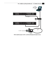
Страница 30: ...that the computer whether communicating over a LAN or directly to the FS1 Ethernet port has a web browser installed If the FS1 will be attached to a LAN talk to your IT administrator and obtain the details about how to configure the FS1 DHCP or static IP explained in this chapter The following figure shows typical LAN connections although your installation may differ 3 If connecting to a network c...

Страница 31: ...tion and Operation Manual Installation Overview FS1 Network Example Two FS1s on a LAN with Laptop for Remote Control 10 100Base T Laptop w Web Browser for FS1 Remote Control Firewall Router WAN ISP Hub 10 100 Base T LAN ...

Страница 32: ...rything and that nothing was damaged during shipment If you find any damage immediately notify the shipping service and supply them with a complete description of the damage AJA will repair or replace damaged items If you find shipping damage contact your AJA dealer or distributor for details on how to have your FS1 repaired or replaced Note Save packing materials and the shipping box If you ever ...

Страница 33: ... be divided into zones separated by software or hardware routers Routers may also be used to connect the LAN to an outside wide area network WAN such as the internet Devices on a LAN have IP addresses which may be fixed and permanent or dynamically assigned by the network DHCP When attaching the FS1 to a LAN talk to your network administrator to find out how they want it connected static IP or DHC...

Страница 34: ...to the browser address bar You should now see the FS1 s browser status screen If the FS1 cannot get an address from the DHCP server on the LAN while the FS1 is set to DHCP via parameter 50 1 the FS1 will automatically drop back to a preset factory IP address of 192 168 0 2 In this instance you can follow these alternate steps to communicate with the FS1 1 Set the computer s Ethernet IP address to ...

Страница 35: ...le entering the information provided to you by your IT administrator Configuring the FS1 with a Static IP Address Note for parameters 50 2 50 3 and 50 4 you will be setting IP addresses that consist of octets separated by a period i e 90 0 180 0 For these parameters the Select button selects the octet and then the Adjust buttons select the desired number Pressing Select again advances to the next ...

Страница 36: ...nsure that you have a valid connection Simply run the Ping utility from a Mac OS X or Windows PC computer attached directly or on the same LAN as the FS1 Mac Ping Procedure 1 Find the Applications Folder and then find the Utilities Folder inside of the Applications Folder 2 Locate the Terminal utility application and double click it 3 On the FS1 go to parameter menu 50 2 and read the IP address 4 ...

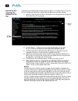
Страница 37: ...are Although the FS1 comes from the factory pre installed with software it may not be as up to date as software posted on our AJA website This topic describes the steps required to upgrade the software in your AJA FS1 Download the Latest FS1 Software Current and past releases of FS1 software are available on the World Wide Web from AJA s website To get the software point your browser to http www a...

Страница 38: ...Firmware button to restart your FS1 6 After restarting the FS1 is running the new software and your existing FS1 configuration prior to the upgrade is preserved Check the FS1 web page again to make sure the software version is displayed at the top of all FS1 web screens If not run the update steps again Notes On some browsers the Retry page may appear even though the upgrade was successful If this...

Страница 39: ... mA to ground will register a logic low Both GPI outputs are 5V TTL compatible sourcing up to 6mA and sinking up to 4mA each Cabling the System Where to Place the FS1 Observe these precautions when placing your FS1 Plan adequate space for cable routing from the back of the chassis Ensure that cable connectors are not stressed and that cables are not bent or crimped When rack mounting or stacking m...

Страница 40: ...ety If the provided plug does not fit into your outlet consult an electrician for replacement of the obsolete outlet Warning Since the Mains plug is used as the disconnection for the device it must remain readily accessible and operable Warning Protect the power cord from being walked on or pinched particularly at plugs convenience receptacles and the point where they exit from the device Warning ...

Страница 41: ...S SMPTE standard With digital audio at maximum possible level before clipping the expected analog audio input level is 24 dBu and the output will be scaled to this level 18 dBu analog 0 dBFS EBU standard With digital audio at maximum possible level before clipping the expected analog audio input level is 18 dBu and the output will be scaled to this level 15 dBu analog 0 dBFS With digital audio at ...

Страница 42: ...dard Operating Level This corresponds to 20dBFS in the digital domain 20 dB of headroom per SMPTE RP 155 so the 24 dBu setting on the FS1 provides proper headroom levels for digital and analog audio Most users in the EU use 0dBu as their Alignment Level This corresponds to 18dBFS in the digital domain 18 dB of headroom per EBU R68 Correspondingly the 18dBu setting on the FS1 provides for this rela...

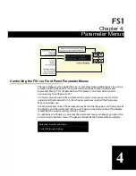
Страница 43: ...the panel controls overall so ensure you ve read and understand that material first In this chapter we discuss each of the Parameter Menus and their use In each parameter screen the parameter number and name appear on the top line of the display and the parameter settings are shown on the bottom line of the display remember the current setting is what is shown As mentioned in Chapter 2 you enter t...

Страница 44: ... the FS1s non volatile memory if they remain unchanged for 3 seconds If a Select or Adjust button is held down continuously the changes will begin to happen automatically with acceleration if applicable Pressing either a Select or Adjust button while on the Status or Screen Saver displays changes the display to the last remembered Control Menu Holding down both the Adjust up and Adjust down button...

Страница 45: ...es 1 The output from Downconverter 2 see block diagram in Chapter 1 is always standard definition 2 Bypass mode is not offered in these cases 3 2 Pulldown 1080pSF 23 98 Input 1080i 59 94 Output 1080pSF 23 98 Input 525i 59 94 Output 1080pSF 24 Input 1080i 60 Output In these cases Bypass mode behaves like Normal mode the output is the same format as the main SDI1 output 1 1 Output Format Description...

Страница 46: ...s parameter performs input video source selection for the FS1 Multiple input sources may be present at all the connectors on the FS1 rear panel but the active input source routed through the FS1 will be the one selected here 1 3 Component Output Description of Choices Parameter Adjustments Normal Default Bypass Follow Input Standard Def Component output follows the 1 1 Output Format parameter sele...

Страница 47: ...l be the one selected here Note If parameter 4 5 Audio Follow Video is set to On then Audio Input selection is independently kept for each separate input SDI 1 SDI 2 Composite S Video and Component If Audio Follow Video is set to Off then another Audio Input selection is used 2 2 Audio Input Description of Choices Parameter Adjustments Stereo Map Channel Map Embed SDI 1 Embed SDI 2 AES unbal Defau...

Страница 48: ...Selects the SDI 1 Channel 2 and maps it to Channel 1 audio out Selects the SDI 1 Channel 3 and maps it to Channel 1 audio out Selects the SDI 1 Channel 4 and maps it to Channel 1 audio out Selects the SDI 1 Channel 5 and maps it to Channel 1 audio out Selects the SDI 1 Channel 6 and maps it to Channel 1 audio out Selects the SDI 1 Channel 7 and maps it to Channel 1 audio out Selects the SDI 1 Chan...

Страница 49: ...er is used with parameter 2 2 when Channel Map is selected to specify the source of the audio output on channel 4 Possible choices are the same as parameter 2 11 Default AES Ch 4 2 15 Audio Map Ch5 This parameter is used with parameter 2 2 when Channel Map is selected to specify the source of the audio output on channel 5 Possible choices are the same as parameter 2 11 Default AES Ch 5 2 16 Audio ...

Страница 50: ...1 2 and maps them to Channel 1 2 audio out Selects AES Channels 3 4 and maps them to Channel 1 2 audio out Selects AES Channels 5 6 and maps them to Channel 1 2 audio out Selects AES Channels 7 8 and maps them to Channel 1 2 audio out Selects Analog Channels 1 2 and maps them to Channel 1 2 audio out Selects Analog Channels 3 4 and maps them to Channel 1 2 audio out Selects Analog Channels 5 6 and...

Страница 51: ...settings 3 1 Component In Description of Choices Parameter Adjustments Beta YPbPr SMPTE YPbPr Default Configure the Component video input source as Beta YPbPr standard definition If the selected Component video source is HD this will default to SMPTE YPbPr Configure the Component video input source as SMPTE YPbPr 3 2 Component Out Description of Choices Parameter Adjustments Beta YPbPr SMPTE YPbPr...

Страница 52: ...elay selection is independently kept for each separate input SDI 1 SDI 2 Composite S Video and Component If Audio Follow Video is set to Off then another Audio Delay selection is used 3 4 NTSC Standard Description of Choices Parameter Adjustments NTSC Default NTSC Japan Select NTSC for North America NTSC standard Select NTSC Japan for Japan s NTSC standard 4 1 Analog Audio Std Description of Choic...

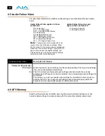
Страница 53: ...l not survive the frame sync function dropping or repeating frames so it needs to be set to lock to the input You can lock to a reference only if that reference is driving both the FS1 and the upstream source of the embedded or AES input to the FS1 Note If parameter 4 5 Audio Follow Video is set to On the Sample Rate Convert selection is independently kept for each separate input SDI 1 SDI 2 Compo...

Страница 54: ...ings When AFV is turned On the source memory settings are written over the current settings Turning AFV Off again will not restore the original settings but instead will result in the source memory settings remaining in effect until edited again 4 1 Analog Audio Std 4 3 Embed Audio Out 4 5 Audio Follow Video Description of Choices Parameter Adjustments Off Default On Normal operation Audio setting...

Страница 55: ...s 4x3 Pillar 14x9 Pillar Default Full Screen LB to Full Wide Zoom Results in 4x3 image in center of screen with black sidebars Results in 14x9 image zoomed slightly to fill a 14x9 image with black sidebars Anamorphic full screen display Image is zoomed to fit the full screen letterbox Using a combination of zoom and stretch the image is sized to fit a 16x9 screen this can introduce a small aspect ...

Страница 56: ...cropped off An AFD code of 9 Pillarbox says that the input video only has content within the center 4 3 area of the picture usually because it originally came from an upconverted SD signal so the downconverter Crop mode would be the best choice There are 16 possible HD AFD codes of which 8 are in common use The FS1 does not process or use SD AFD codes FS1 AFD processing passing removing and re ins...

Страница 57: ... 47 FS1 Installation and Operation Manual 5 2 Downconvert Mode Downconvert Illustrations 1 6 9 Downconvert Illustrations FS1 Anamorphic Letterbox 4 3 16 9 Downconverts To These displays on 4 3 Crop 14 9 ...

Страница 58: ...io Convert Description of Choices Parameter Adjustments Off Default Letterbox H Crop Pillarbox V Crop 14 9 Turns aspect ratio conversion Off Converts 16 9 Anamorphic video to Letterbox video Converts 16 9 Anamorphic video to 4 3 Standard video crops left and right edges of video Converts 4 3 Standard video to 16 9 Anamorphic video Converts Letterbox video to 16 9 Anamorphic video Converts 16 9 Ana...

Страница 59: ...5 5 Downcvt AFD Dflt Description of Choices Parameter Adjustments Hold Last Default Letterbox 14x9 Anamorphic Crop Use the last AFD code detected and continue to use its aspect ratio selection until a new AFD code is detected again in the SDI meta data When an AFD code isn t present switch the downconverter mode to Letterbox When an AFD code isn t present switch the downconverter mode to 14x9 When...

Страница 60: ...rting the appropriate AFD code will be chosen based on the upconvert mode The FS1 always inserts a Box 16 9 center AFD code 4 which indicates that the HD image has an aspect ratio greater than 16 9 as a vertically centered letterbox within the 16 9 frame The FS1 always inserts a Full Frame AFD code 8 which indicates that the HD image is full frame with an aspect ratio that is 16 9 The FS1 always i...

Страница 61: ...arameter specifies a number of lines to offset moving the screen up to a half a frame up or down 6 1 Genlock Source Description of Choices Parameter Adjustments Reference Default Input Free run Use the signal on the Ref connector as the genlock source Use the signal on the currently selected input as the genlock source Free run mode FS1 syncs to its own timebase not locked to an external source 6 ...

Страница 62: ...selected here 7 1 for the Sidebar must be an HD signal and it must be the same format as that selected for parameter 1 1 Output Format The sidebar width created by the keyer is specified in parameter 7 2 Notes 1 It is normal for SD sources used for the sidebar fill to sometimes have asymmetrical edges if SD video isn t cropped to real video This can be seen in some cases where digital video was di...

Страница 63: ...appears the sidebars will not appear on the video output The Status menu displays sidebar SB status information to help you find the cause of the conflict 10 1 Proc Amp This parameter turns the Proc Amp On and Off When it is On you can set additional parameters 10 1 to 10 5 to control video gain black level hue and saturation Note Proc Amp parameter settings are independently kept for each separat...

Страница 64: ...from black and white to 1 5 times chroma in steps of 01 each time an Adjust button is pressed 10 2 Proc Amp Gain Description of Choices Parameter Adjustments Variable Adjustment range increments from zero to 1 5 in 01 steps Default unity 1 0 10 3 Proc Amp Black Description of Choices Parameter Adjustments Variable Adjustment range increments from 20 IRE to 20 IRE in 5 steps Default unity 0 IRE 10 ...

Страница 65: ...tion is used This note applies to parameters 20 0 through 20 8 20 1 Audio Level Ch1 This parameter adjusts the audio level of audio channel 1 18dB in steps of 0 5 dB Note If parameter 4 5 Audio Follow Video is set to On then Audio Level Ch1 selection is independently kept for each separate input SDI 1 SDI 2 Composite S Video and Component If Audio Follow Video is set to Off then another Audio Leve...

Страница 66: ... audio level of audio channel 5 18dB in steps of 0 5 dB Parameter adjustments are the same as for 20 1 20 6 Audio Level Ch6 This parameter adjusts the audio level of audio channel 6 18dB in steps of 0 5 dB Parameter adjustments are the same as for 20 1 20 7 Audio Level Ch7 This parameter adjusts the audio level of audio channel 7 18dB in steps of 0 5 dB Parameter adjustments are the same as for 20...

Страница 67: ...s to parameters 21 1 through 21 8 21 2 Audio Phase Ch2 This parameter selects whether audio phase is normal same as passed from the input or inverted on channel 2 Parameter adjustments are the same as 21 1 21 3 Audio Phase Ch3 This parameter selects whether audio phase is normal same as passed from the input or inverted on channel 3 Parameter adjustments are the same as 21 1 21 4 Audio Phase Ch4 T...

Страница 68: ...1 captions to CEA 708 format and insert the VANC packets into the converted HD video stream This is a complete translation from CEA 608 format to CEA 708 format including the embedded SD captions When set to On and using the Downconverters the FS1 will automatically intercept and reformat the SD caption data in the incoming CEA 708 VANC packets and output it on line 21 of the standard definition o...

Страница 69: ...led HD DTV or 708 captioning The data formatting and encoding for 708 captions is very different from the data contained in 608 SD captioning reflecting the added features and capabilities available with the CEA 708 standard The FS1 UpConverter automatically translates incoming line 21 captions to CEA 708 format and inserts the VANC packets into the converted HD video stream This is a complete tra...

Страница 70: ...n This is used to blank Line 21 caption data Passes input video Line 21 to the converter and to the outputs The FS1 looks for Line 21 caption data on the video input If present Line 21 is blanked before video conversion occurs If no caption data is found Line 21 passes to the converter 35 1 Remote Control Description of Choices Parameter Adjustments LOCAL REMOTE Default REMOTE ONLY LOCAL ONLY Allo...

Страница 71: ...r to the default password which is password 4 If you select Basic without first setting the password via web the default password will be used See parameter 99 0 for more about the password 5 After you select Basic a password is required for webUI browser access to the FS1 Passwords cannot be entered at the front panel but must be entered via web browser Your browser will prompt for a username pas...

Страница 72: ...the video input if a GPI trigger is received at pin 1 When either SDI1 In SDI2 In Composite In S Video In or Component In are selected the input video source selected will remain selected even after the GPI trigger is released deactivated FS1 performs upconversion of SD source to 14x9 pillarbox see parameter 5 1 FS1 performs upconversion of SD source to full screen see parameter 5 1 FS1 performs u...

Страница 73: ...hen either SDI1 In SDI2 In Composite In S Video In or Component In are selected the input video source selected will remain selected even after the GPI trigger is released deactivated FS1 performs upconversion of SD source to 14x9 pillarbox see parameter 5 1 FS1 performs upconversion of SD source to full screen see parameter 5 1 FS1 performs upconversion of SD source from letterbox to full see par...

Страница 74: ...3 if Composite is selected as the main video input FS1 generates a GPI 1 output trigger on pin 3 if S Video is selected as the main video input FS1 generates a GPI 1 output trigger on pin 3 if Component is selected as the main video input 39 1 GPI 2 OUT Description of Choices Parameter Adjustments No Action Default Alarm No Video No Ref Vid In SDI1 Vid In SDI2 Vid In Cmpst Vid In S Vid Vid In Cmpn...

Страница 75: ...io signals appear at the FS1 audio outputs When you set the parameter to an audio tone that tone gets switched into the audio outputs 40 1 Freeze Output Description of Choices Parameter Adjustments Off Default On Normal operation The FS1 outputs video from the input The FS1 captures and freezes the most current video frame and displays it on the outputs as long as this parameter is set to On 41 2 ...

Страница 76: ... octet You ll notice that after completing the edit on the last octet the display will blink this is an indication that the edited IP address is about to be saved You can save the edited IP address press the Select arrow up button to save or choose not to save by pressing the Select down arrow button 50 1 IP Config Description of Choices Parameter Adjustments DHCP Default Static Addr Default Addr ...

Страница 77: ...rol this FS1 via a web browser Also without a proper gateway defined the discovery feature Available FS1s Click to Refresh on the Network web page will not work correctly and list other FS1s on the network Please read the Note about editing IP addresses in parameter 50 2 as it also applies to parameters 50 3 and 50 4 50 3 Subnet Mask Description of Choices Parameter Adjustments variable Using the ...

Страница 78: ...e value associated with the FS1 s internal network adapter MAC addresses are also known as hardware addresses or physical addresses MAC addresses uniquely identify an Ethernet adapter on a LAN MAC address format MM MM MM SS SS SS The value is 12 digit hexadecimal where the first half identifies the manufacturer and the second half identifies the unique serial number 50 5 System Name Description of...

Страница 79: ...l be sent When the SNMP Trap Destination IP addresses are edited you can abort the editing process by backing out press the Select down arrow button repeatedly until the edit passes the first octet You ll notice that after completing the edit on the last octet the display will blink this is an indication that the edited IP address is about to be saved You can save the edited IP address by pressing...

Страница 80: ...rap Destination IP addresses are edited you can abort the editing process by backing out press the Select down arrow button repeatedly until the edit passes the first octet You ll notice that after completing the edit on the last octet the display will blink this is an indication that the edited IP address is about to be saved You can save the edited IP address by pressing the Select up arrow to s...

Страница 81: ... 1 Power Supply Alarm This parameter controls how the FS1 alarm responds to power supply failures The default Normal is that the alarm will be triggered anytime either of the internal power supplies fails or is disconnected from a power source becomes unplugged If the FS1 will only be connected to one power cord you can suppress this alarm 51 5 SNMP Trap Port 2 Description of Choices Parameter Adj...

Страница 82: ...mat or is not detected at all 2 The reference signal is required due either to 1 1 Output format set to Follow Ref or 6 1 Genlock Source set to Reference If you want the FS1 alarm to only trigger on hardware failures you can suppress the Format Alarm 60 2 Format Alarm Description of Choices Parameter Adjustments Normal default Suppress Alarm triggers if the format of the selected input video signa...

Страница 83: ...eboots the FS1 1 Use the Select buttons to scroll to parameter 90 0 Reboot 2 Press the top Adjust button to advance to the UP to Confirm menu field Press any other button to cancel 3 Press the top Adjust button again to advance to the Both Reboot menu field 4 Press both Adjust buttons at the same time to reboot The display shows Rebooting goes dark momentarily and then shows the percentage of prog...

Страница 84: ...s the current FS1 configuration to a Preset Configuration There are ten available presets 1 10 To store the current FS1 configuration 1 Use the Select buttons to scroll to parameter 92 1 Preset Save 2 Use the Adjust buttons to select a preset default 1 3 Press the top Select button to advance to the UP Save menu field Press the bottom Select button to cancel 4 Press the top Adjust button to save t...

Страница 85: ...n buttons at the same time Note To set a single parameter to its factory default value go to that parameter s Adjust menu and hold down both the Adjust up and Adjust down buttons at the same time 35 1 Remote Control 51 2 SNMP Trap Dest 1 35 3 Password 51 3 SNMP TrapPort 1 40 1 Freeze Output 51 4 SNMP Trap Dest 2 50 1 IP Config 51 5 SNMP Trap Port 2 50 2 IP Address 60 1 Pwr Supply Alarm 50 3 Subnet...

Страница 86: ...76 ...

Страница 87: ...er its IP address in the web browser The IP address is defined in parameter 50 2 of the FS1 s Network parameter menus please note that parameters 50 1 through 50 4 must all be configured correctly to access the FS1 on your network If the FS1 is using DHCP the default you can find the IP address by pressing the Status button on the FS1 front panel until the Network Status display is shown or you ca...

Страница 88: ...r you to reference we ll list the definitions redundantly here so you don t have to flip back and forth between chapters FS1 Web Interface Main Status Screen Controlling Multiple FS1s From the Network screen you can see at a glance all of the FS1 devices present on the same local LAN as the current FS1 you are controlling At the bottom of the screen under Available FS1s Click to Refresh the system...

Страница 89: ...d Reset all FS1 parameters to Factory Values This functions the same as the FS1 front panel parameter 99 0 another way to reset to factory values Audio and Video I O Screen The Audio and Video I O screen sets the audio and video input and output formats as well as other related parameters FS1 Web Interface Audio and Video I O Screen Input Format Information only field that displays the format the ...

Страница 90: ...hedigital AES EBU Audio connectors 8 ch as the audio input source Select the Analog Audio connector DB25 8 ch as the audio input source 59 94 23 98 default 60 24 50 25 Select the 59 94 23 98 item if your desired rate is either 59 94 or 23 98 Select the 60 24 item if your desired rate is either 60 or 24 Select the 50 25 item if your desired rate is either 50 or 25 PAL Beta YPbPr SMPTE YPbPr default...

Страница 91: ...Component output follows the format of the selected input Note Bypass mode does not work when the input is 1080pSF24 and output is 1080i60 3 2 pulldown mode Note 2 The signal type of the component output is defined in another selection Component Out above in the screen also parameter 3 2 from the parameter display The output from Downconverter 2 see block diagram in Chapter 1 is always standard de...

Страница 92: ...If a selected analog input is lost while Freeze is enabled the output will not be valid video Off default SDI 1 SDI 2 Component Turns the Sidebar Keyer Off Turns the Sidebar Keyer On and selects SDI 1 as the HD input source for the Sidebar keyer Turns the Sidebar Keyer On and selects SDI 2 as the HD input source for the Sidebar keyer Turns the Sidebar Keyer On and selects Component In as the HD in...

Страница 93: ... level and phase The actual appearance of this page can change reflecting Audio Output choices For example if the Level control is not set to Unity then controls will appear allowing you to set the levels of the eight channels All of the sliders on this page provide two ways to enter a value Click and drag the slider Click on the numeric value above the slider enter a new value and press Enter to ...

Страница 94: ...udio settings must be made separately from any video settings they are not associated automatically The FS1 remembers the audio settings associated with the currently selected input Whenever an input is selected the corresponding audio settings will be recalled This allows you to set up specific audio settings for the different video inputs i e perhaps the SDI 1 has a specific embedded audio chann...

Страница 95: ...converter downconverter and SD Aspect Ratio converters FS1 Web Interface Convert Mode Screen Stereo Map Channel Map Embed SDI 1 Embed SDI 2 AES unbal Default Analog For the 8 channels of embedded audio out select stereo inputs according to Audio Map parameters 2 21 through 2 24 Any channel pair 4 pair total can be mapped to 24 different choices For the 8 channels of embedded audio out select and m...

Страница 96: ...ically selects the best downconvert mode based on the input video s Active Format Description AFD code If the input video is not carrying an AFD VANC code the downconverter defaults to the mode specified in parameter menu 5 5 Downconvert AFD Default Off default Letterbox H Crop Pillarbox V Crop 14x9 Turns aspect ratio conversion Off Anamorphic converted to Letterbox 16 9 to 4 3 Anamorphic 16 9 scr...

Страница 97: ...ndicates that the HD image is full frame with an aspect ratio that is 16 9 The FS1 always inserts a 4 3 center AFD code 9 which indicates that the HD image has a 4 3 aspect ratio as a horizontally center pillarbox image within the 16 9 frame The FS1 always inserts a 16 9 with complete 16 9 image protected AFD code 10 which indicates that the HD image is full frame with a 16 9 aspect ratio and all ...

Страница 98: ...umber of pixels to offset from zero to full line width Horizontal Output Fine Timing Further adjusts the horizontal analog output timing only in finer increments than 6 2 above in this case by sub pixels Each adjustment of the control from 0 to 127 adjusts the timing by 1 128th of a pixel Note This fine timing control only affects the analog outputs Vertical Output Timing lines 6 3 This slider adj...

Страница 99: ... separate input SDI 1 SDI 2 Composite S Video and Component ProcAmp Enable 10 1 All Resets all Proc Amp settings to Unity regardless of their current settings Gain 10 2 Slider changes video gain from black to 1 5 times luma in steps of 01 Blacklevel 10 3 Slider adjusts video black level from 20 IRE to 20 IRE in 5 steps Hue 10 4 Slider adjusts video color hue through 360 degrees color wheel Slider ...

Страница 100: ... caption data in the incoming CEA 708 VANC packets and output it on line 21 of the standard definition outputs When Off translation is not performed Upconvert Line 21 31 1 Captioning Status This field is a read only informational display that shows whether Closed Caption data is present on the currently selected video input FS1 Web Interface Caption Screen Blank default Pass Auto blank In UpConver...

Страница 101: ...Preset Configuration To recall a preset click the Recall button associated with to the right of the preset name A dialog box asks you to confirm the recall click OK to recall Cancel to cancel Caution When you click Yes to recall a Preset Configuration the recalled preset immediately replaces the system s existing configuration All previous settings are lost unless you have previously stored them i...

Страница 102: ...owser options If you export multiple files a number gets appended to ensure a unique file name The file size is usually about 2 5 Megabytes Import All Use this function to browse for and import a previously exported all presets file from your computer A dialog box warns you that the operation will overwrite all 10 current preset contents with the contents stored in the file Click OK to import the ...

Страница 103: ...Setting alphanumeric display brightness Resetting All FS1 Parameters to Factory Values FS1 Web Interface Miscellaneous Screen Identify LED Screen Saver 70 1 On Off default Turn the front and rear panel ID LED lights On Turn the front and rear panel ID LED lights Off AJA Logo default System Name Disabled Display horizontally rolling AJA logo after 60 minutes of FS1 front panel button inactivity Dis...

Страница 104: ...s Composite In as the video input if a GPI trigger is received at pin 1 FS1 selects S Video In as the video input if a GPI trigger is received at pin 1 FS1 selects Component In as the video input if a GPI trigger is received at pin 1 When either SDI1 In SDI2 In Composite In S Video In or Component In are selected the selected input video source will remain selected even after the GPI trigger is re...

Страница 105: ...en after the GPI trigger is released deactivated FS1 performs upconversion of SD source to 14x9 pillarbox see parameter 5 1 FS1 performs upconversion of SD source to full screen see parameter 5 1 FS1 performs upconversion of SD source from letterbox to Full see parameter 5 1 FS1 performs upconversion of SD source to a wide zoom see parameter 5 1 FS1 performs upconversion of SD source to 4x3 pillar...

Страница 106: ...will not trigger a GPI 2 output trigger regardless of event FS1 will generate a GPI 2 output trigger on pin 4 if an internal alarm condition occurs GPI DE 9 Connector See Chapter 2 for alarm descriptions FS1 will generate a GPI 2 output trigger on pin 4 if no video is detected at its selected input FS1 will generate a GPI 2 output trigger on pin 4 if no video is detected at the Ref input FS1 gener...

Страница 107: ...et will not see parameter 99 0 for information 3 Changing Authentication to Disabled resets the System Password parameter to the default password which is password 4 If you select Basic Password authentication the default password will initially be used until you set a password with Set Password 5 After you select Basic Password authentication your browser immediately requires a password before fu...

Страница 108: ...must match and the password will not be final until the Change Password button is clicked these controls will not be visible if Authentication is set to Disabled Display Intensity 70 2 Either by using the slider or by entering a value you can dim or brighten the alphanumeric display and activity indicator LEDs in steps from 1 dim to 8 brightest Reset All FS1 Parameters To Factory Values 99 0 As th...

Страница 109: ... signals are turned off and the normal video signals appear at the FS1 video outputs When you set the parameter to a test pattern that pattern gets switched into the video outputs Available test signals are Black 75 Bars or 100 Bars Audio SG 41 3 This parameter determines the audio signal output from the FS1 s internal audio test signal generator OFF default silence or 1 kHz tone When you set the ...

Страница 110: ...k the Update button the FS1 IP address will change and the browser will display a redirecting to page which should send the browser to the new IP address entered You can also click on a link on the redirect page IP Address 50 2 Enter an IP address compatible with your LAN if you have one When you network the FS1 to a computer this is the IP address that you ll enter in the computer s web browser t...

Страница 111: ...0 5 are listed and clicking on any of these will bring up the Status screen of that FS1 Note the FS1 you control may be running a different software version so screens may look different As a rule it s wise to have all your FS1 devices running the most current software and the same version Also without a properly configured default gateway whether you have a router gateway or not the discovery fea...

Страница 112: ...ate submit button to update the FS1 with the IP address entered here A Port number for the TCP IP port to be used for trap messages from the FS1 to the NMS must also be specified UDP Port 162 is the default Two sets of Trap Destination IP and Port numbers are provided so you can send trap messages in parallel to two NMS Note Illegal data such as out of range addresses or text entered on the SNMP w...

Страница 113: ... 4 alarms may be sent by the FS1 to the client NMS as a trap message Power supply failure or disconnection fs1PSAlarm see parameter 60 1 Reference video fs1REFAlarm see parameter 60 3 Format fs1FMTAlarm see parameter 60 2 Temperature of FS1 is over limit internally fs1OVRAlarm 51 1 SNMP Enable Description of Choices Parameter Adjustments Disable Default Enable 1 Enable Both When set to Disable the...

Страница 114: ... 51 2 SNMP Trap Dest 1 Description of Choices Parameter Adjustments variable Using the Adjust buttons enter the IP address of the destination where SNMP command messages called traps will be sent This is usually an SNMP client NMS or Network Management System somewhere on your LAN Default 192 168 0 3 51 4 SNMP Trap Dest 2 Description of Choices Parameter Adjustments variable Using the Adjust butto...

Страница 115: ...MPTE 274 SD component composite YC S Video Video A D D A 12 bits 2x oversampled HD 4x oversampled SD Audio Inputs and Outputs 8 Channel Balanced 25 pin D Tascam pinout 8 Channel AES BNC 8 Channel SDI HD SDI Embedded Audio levels 12dBu 15dBu 18dBu 24dBu Full Scale Digital LAN 10 100 automatic configuration Automatic cable crossover auto MDI X Embedded web server HTTP v1 1 SNMP VTECS protocol for Re...

Страница 116: ...ndix B for pinout and specifications Physical Width 17 25 43 81cm Depth 12 5 31 75cm Height 1RU 1 75 4 44cm Weight 6 5lbs 2 94kg Operating temperature range 0 40 degrees C Convection cooled Power Voltage 100 240 VAC Power Consumption 25W 30W maximum Two independent power supplies fully redundant diode isolated ...

Страница 117: ...n pins 6 8 I O Ground 1 Input 2 and Output 2 share a common isolated ground on pins 7 9 I O Ground 2 Pin 5 local chassis ground may only be used as a reference when isolation is not required Both GPI inputs are internally pulled high through a 10K ohm resistor to an isolated 5V supply so that a relay contact closure or any device sinking at least 0 4 mA to ground will register a logic low Both GPI...

Страница 118: ...register the logic low that triggers the GPI input You can connect the outputs to TTL buffers that communicate the GPI output logic levels to other devices For example you could use an opto isolator controlling a relay to activate other equipment as shown below Typical GPI Input and Output Connections GPI Output 1 GPI Input 1 GPI GND 1 V xmit xmit Optical Relay SSR To Tally Lamp etc ...

Страница 119: ...tions Connector Pinout The two DB25 connectors on the FS1 rear panel support a TASCAM style cable snake for balanced 8 channel analog audio The pinout is the same for both input and output connectors each following the TASCAM DB 25 standard shown in the drawing above ...

Страница 120: ...110 ...

Страница 121: ...adio or television reception which can be determined by turning the equipment off and on the user is encouraged to try to correct the interference by one or more of the following measures Reorient or relocate the receiving antenna Increase the separation between the equipment and receiver Connect the equipment into an outlet on a circuit different from that to which the receiver is connected Consu...

Страница 122: ...PUBLIC DENMARK ESTONIA FINLAND FRANCE GERMANY GREECE HUNGARY IRELAND ITALY LATVIA LITHUANIA LUXEMBOURG MALTA NETHERLANDS POLAND PORTUGAL ROMANIA SLOVAKIA SLOVENIA SPAIN SWEDEN UNITED KINGDOM ICELAND LICHTENSTEIN NORWAY SWITZERLAND Declaration of Conformity Marking by this symbol indicates compliance with the Essential Requirements of the EMC Directive of the European Union 2004 108 EC This equipme...

Страница 123: ... produit risque de créer des interférences radioélectriques il appartiendra alors à l utilisateur de prendre les mesures spécifiques appropriées Korea KCC Compliance Statement Taiwan Compliance Statement This is a Class A product based on the standard of the Bureau of Standards Metrology and Inspection BSMI CNS 13438 Class A Japanese Compliance Statement This is a Class A product based on the stan...

Страница 124: ...incluidas en la documentación Aviso Leia e siga todos os avisos e instruções assinalados no produto ou incluídos na documentação Avviso Leggere e seguire tutti gli avvisi e le istruzioni presenti sul prodotto o inclusi nella documentazione Warning Do not use this device near water and clean only with a dry cloth Avertissement N utilisez pas cet appareil près de l eau et nettoyez le seulement avec ...

Страница 125: ...iso Non installare vicino a fonti di calore come termosifoni diffusori di aria calda stufe o altri apparecchi amplificatori compresi che emettono calore Warning Refer all servicing to qualified service personnel Servicing is required when the device has been damaged in any way such as power supply cord or plug is damaged liquid has been spilled or objects have fallen into the device the device has...

Страница 126: ...ieten kann es Störungen des Radio und Fernsehempfangs verursachen In diesem Fall muss der Benutzer alle notwendigen Maßnahmen ergreifen die möglicherweise nötig sind um die Störungen auf eigene Rechnung zu beheben Precaución Este es un producto clase A El uso de este equipo en áreas residenciales puede causar interferencias nocivas en cuyo caso se requerirá que los usuarios tomen cualquier medida ...

Страница 127: ...i e o venduti dal produttore Warning Do not defeat the safety purpose of the polarized or grounding type plug A polarized plug has two blades with one wider than the other A grounding type plug has two blades and a third grounding prong The wide blade or the third prong are provided for your safety If the provided plug does not fit into your outlet consult an electrician for replacement of the obs...

Страница 128: ...e della presa obsoleta Warning Since the Mains plug is used as the disconnection for the device it must remain readily accessible and operable Avertissement Puisque la prise principale est utilisée pour débrancher l appareil elle doit rester aisément accessible et fonctionnelle Warnung Da der Netzstecker als Trennvorrichtung dient muss er stets zugänglich und funktionsfähig sein Advertencia Puesto...

Страница 129: ...chassis There are no user serviceable parts inside Opening the chassis will void the warranty unless performed by an AJA service center or licensed facility Avertissement Ne pas ouvrir le châssis Aucun élément à l intérieur du châssis ne peut être réparé par l utilisateur La garantie sera annulée si le châssis est ouvert par toute autre personne qu un technicien d un centre de service ou d un étab...

Страница 130: ...120 Warning To meet safety regulations for leakage current connect the FS1 dual power supplies to separate branch circuits ...

Страница 131: ... the even lines in a second scan 1080p Refers to a picture resolution of 1 920 vertical pixels by 1 080 horizontal pixels The p stands for progressive scanning This format works on the same principle as 720p the only difference is that in this type there are more pixels and the resolution is better 1080psf 1080psf differs from 1080p defined previously PSF is an acronym for Progressive Segmented Fr...

Страница 132: ...ometimes referred to as barn doors Codec A short term used for both Compressor decompressor and Coder decoder In terms of Final Cut Pro and most editing and graphics applications codec generally means Compressor decompressor which whether hardware or software converts video and audio signals to and from a compressed digital format Coder decoder is generally a device that converts analog video and ...

Страница 133: ... Offering twice the vertical and horizontal picture resolution of standard definition an HD picture is much sharper HDTV has a widescreen aspect ratio of 16 9 HD formats 1080i and 720p both offer reduced motion artifacts like ghosting and dot crawl HD SDI Refers to a high definition signal provided on a serial digital connection High Definition A video format consisting of either 720 active lines ...

Страница 134: ...on Television Standard Definition Television pictures are higher quality than NTSC however they do not reach the quality and resolution of HD SDTV is based on 480 lines of vertical resolution available with both interlaced and progressively scanned formats SD SDI Refers to a standard definition signal provided on a serial digital connection Sidebars See Barn Doors Upconverting Process by which a s...

Страница 135: ...een 79 Audio Control Screen 83 Audio Delay ms 4 2 85 Audio Follow Video 4 5 81 84 Audio In 2 2 80 Audio Input Output 30 Audio Level Settings 31 Audio Out Level 20 1 84 Audio Out Phase 21 0 84 Audio SG 41 3 99 Authentication 35 3 96 Aux LED 11 Available FS1s Click to Refresh 101 B Back Panel 14 Barn Doors Defined 122 Blacklevel 10 3 89 Block Diagram 3 Box Contents Shipping 3 5 22 Browser Control 27...

Страница 136: ...splay Status 8 9 Display Intensity 70 2 98 Display Front 8 Downconvert AFD Default 5 5 86 Downconvert Mode 5 2 86 Downconvert Defined 122 DTV Digital Television Defined 122 E EFTA and EU Compliance 112 Embed Audio Out 4 3 81 Embedding Defined 123 Ethernet Connections 23 Ethernet LAN Connector 15 Events Ref Signal 12 Export 92 Export All 92 F FCC Compliance 111 Features 1 Format Compatibility Table...

Страница 137: ...d 123 M Mini DIN 15 Miscellaneous Screen 93 Mode 11 Mounting the Chassis 23 N Netmask 50 3 101 Network Connections 3 23 Network Screens 100 NTSC In Out Connection 16 NTSC Standard 3 4 80 O Output Format 9 Output Format 1 1 79 Output Selection 9 Overview 1 Browser Control 3 Panel 2 P P S 1 and P S 2 Connectors 14 Packaging 5 PAL In Out Connection 16 Panel Illustrations 7 Panel Overview 2 Panel Fron...

Страница 138: ...ar Keyer 52 7 2 Sidebar Edge 53 70 1 Screen Saver 73 70 2 Display Intensity 73 80 1 Serial Number 73 80 2 Software Version 73 90 0 Reboot 73 91 1 Preset Recall 74 92 1 Preset Save 74 99 0 Factory Settings 75 Physical Requirements 23 Ping Test the Network Connection 26 Power 1 LED 11 Power Consumption 30 Power Cord 5 Power Requirements 30 Power Temp Status 9 Preset Configurations 74 Presets Screen ...

Страница 139: ... Temp 9 Sidebar 9 Video Format 9 Status Button 8 9 Status Display 9 Status Screen 78 Styling 2 Supported Web Browsers 77 S Video In Out Connectors 15 16 Synchronizing Other Equipment 17 System Block Diagram 3 System Name 50 5 94 T Taiwan Compliance 113 TCP IP 23 Test Signal Screen 99 Trap Receivers 51 2 to 51 5 102 U Unpacking 5 22 Upconvert Line 21 31 1 90 Upconvert Mode 5 1 86 Upconverting Defin...

Страница 140: ...130 ...

Отзывы: