FS-HDR Frame Synchronizer/Converter/HDR-WCG Processor v1.0r1 17 www.aja.com
Chapter 2 – Controls, Indicators, and
Connections
Overview
The controls, indicators, and connectors illustrated and described in this
chapter allow you to connect, operate, and monitor the FS-HDR system and to
troubleshoot problems if you encounter them. Becoming familiar with the front
and rear panels also simplifies system installation, setup, and operation.
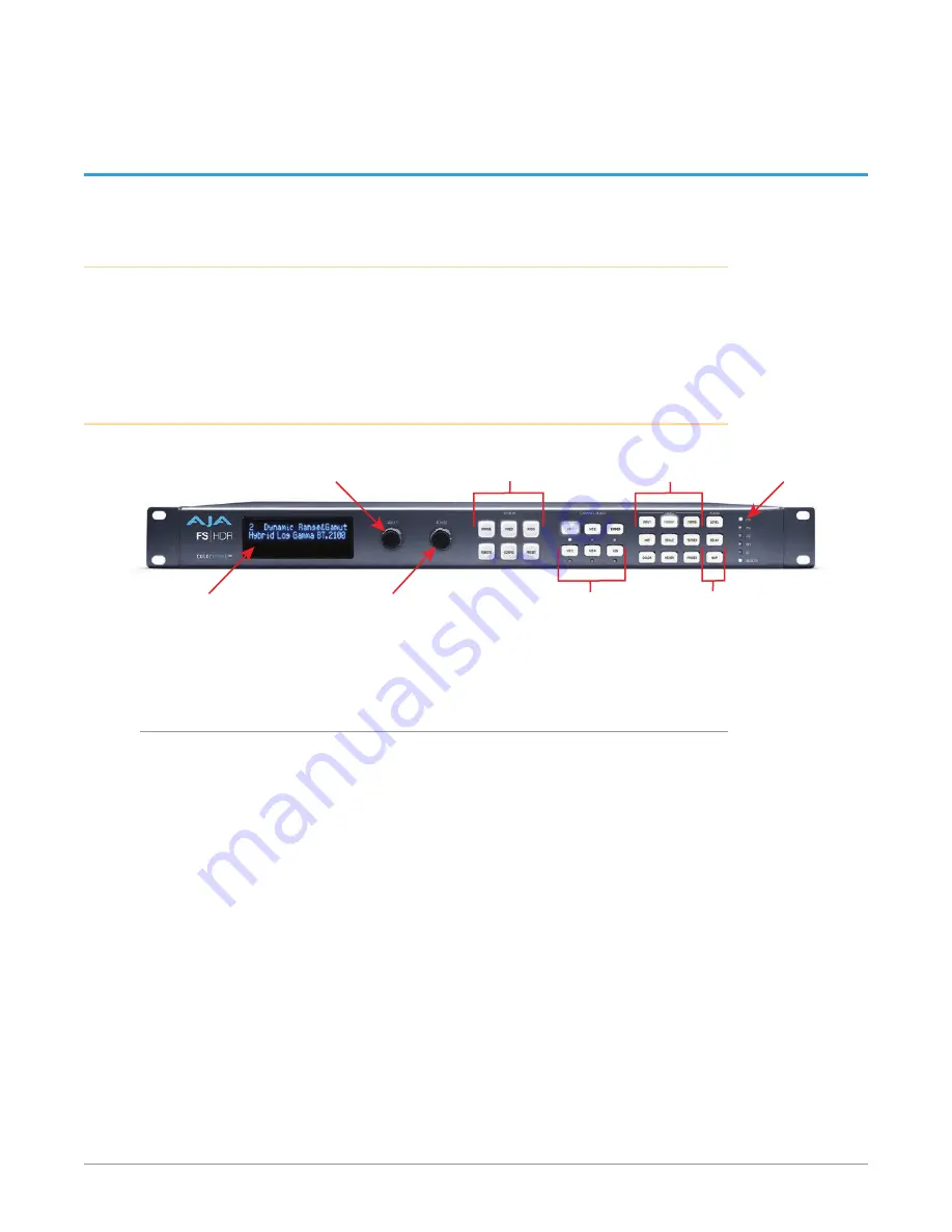
Front Panel Description
System Selection Buttons:
Press a button to select
a System Category
Select Knob:
Scrolls and selects menus.
Push to undo changes.
Video Menu Group
Selection Buttons
Channel Selection Buttons:
Press a button to select a
Video Processor or
Type of Audio
(Selection LED Lights)
Audio Menu Group
Selection Buttons
Status
Indicator
LEDs
Adjust Knob:
Changes selected value.
Hold down for default value.
Alphanumeric
Display
Front Panel Layout and Operation
The FS-HDR’s front panel control system is designed to be quick and easy to use.
The alphanumeric display on the left shows status and parameter information.
SELECT and ADJUST knobs provide fast menu scrolling, parameter selection and
adjustment. Status LEDs on the right report important system information.
The buttons on the front panel operate interactively. At the center of the panel
are System Selection buttons, which provide direct access to parameter menus
that control basic FS-HDR operation (like setting the output frame rate or
selecting Single or Four Channel Mode). In addition, the STATUS button brings
up menus that report FS-HDR status information, and the PRESET button displays
Preset selection menus for rapid reconfiguration. When a System Selection
button is pressed, the parameter menu that was last selected from that group will
be displayed. Pressing any of these buttons de-selects all other SYSTEM buttons,
CHANNEL SELECT buttons, VIDEO menu group buttons, and AUDIO menu group
buttons to the right.
The four VID1-4 Channel Selection buttons to the right allow immediate access
to separate parameter menus for each Video Processor (when in Four Channel
Mode). The button for the currently selected Video Processor is illuminated. In
Single Channel Mode pressing any of the four buttons will light the VID1 button,
indicating that single Video Processor is selected for control. After a Video


