Before execution
Execution 1/2
Location decision
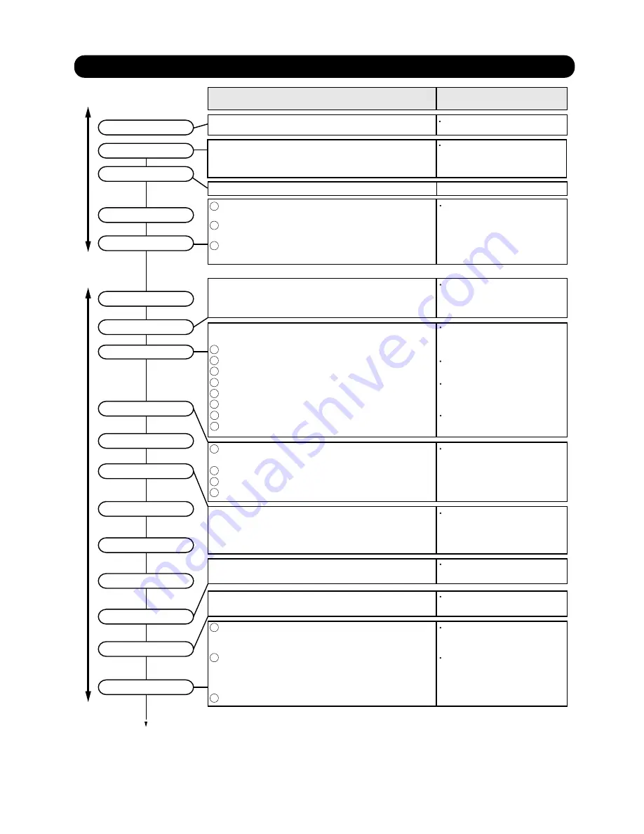
Execution procedure and precautions
Reason
01-01
1-1
EXECUTION PROCEDURE AND EXECUTION PRECAUTIONS
1. TEST RUN
Sleeve and insert work
Indoor unit installation
Refrigerant piping work
Drain piping work
Duct work
Heat insulation work
Electrical work
Outdoor unit foundation work
Outdoor unit installation
Refrigerant piping connection work
Air tightness test
Vacuum drying
Use new refrigerant piping of the thickness specified by the
D&T manual.
Since R410A dedicated tools are necessary, prepare them in
advance.
Absolutely avoid use of existing piping. If use of existing
piping is unavoidable, the piping must be cleaned.
Use pipe that is not dirty inside.
Confirm the design for the piping ( Diameter, Thickness )
When the pipe is left standing, protect it.
Confirm the angle of separation tube and header correctry.
Finish flaring exactly.
Confirm the width across flats dimension and shape of flare nuts.
Always blow nitrogen while brazing.
Perform flushing before connecting the equipment.
Always make the downward slope of the drain pipe 1/100 or
greater and make the horizontal length within 20m.
Use hard polyvinylchloride pipe as the drain pipe.
Support the drain pipe between 1.5 to 2.0m.
Use pipe of 1 rank up (VP30 or greater) as central piping.
Prevention of water leakage
Foreign matter, water, etc. in the
piping will cause faulty cooling and
compressor trouble.
Incorrect pipe diameter will cause
faulty cooling
Incorrect angle of separation tube or
header will be cause poor cooling or
refrigerant noise problem
Refrigerant leakage will cause low
performance and abnormal stopping
Prevention of water leakage
Prevention of water leakage
Refrigerant leakage will cause low
performance and abnormal stopping.
Refrigerant leakage will cause low
performance and abnormal stopping.
Mixing in of vacuum pump oil by
reverse flow will cause equipment
trouble.
Always use a level and keep the indoor unit level.
If the equipment is tilted toward the drain port, install it so that the tilt
is within 10mm. Excessive tilt will cause water leakage.
Select the size of the heat insulating material according to the ambient
temperature and relative humidity of the refrigerant.
Use a heat insulating material having a heat conductivity of 0.043W/
(m
.
k) or less.
When making flare connections always use a torque wrench and
tighten the flare nut positively to the specified torque.
Pressurize the product with nitrogen gas up to the design pressure
and conduct a 24Hr air tightness test.
Install a vacuum pump with reverse flow check mechanism or a
reverse flow check adaptor to a conventional vacuum pump and
use.
Pump down sufficiently.
Approximately 1 hour or longer after -0.10MPa reached.
Allow to stand for approximately 1 hour after stopping the vacuum
pump and confirm that the needle does not return.
Air purging using refrigerant is strictly prohibited.
1
1
1
2
3
2
3
4
5
6
1
2
3
4
2
3
Vaccuming mode
This function is used for vacuuming the indoor unit and the connection piping.
Note: For starting Vaccuming mode, the refrigerant address setting has to be finished.
When the [vacuuming mode] is set, <Push switch setting, F3:21>
EEV of connected all indoor units opens.
So, the vacuuming indoor unit and piping becomes easier.
When the vacuuming ends, please turn off the power supply for all of the indoor units and
the outdoor unit, [vacuuming mode] is released.
*
recommend the vacuuming mode
Do not install the units in the place not recommended in the installation
manual.
The performance may drop significantly
due to the protection controlling
Use of a refrigerant other than the
specified refrigerant will invite
equipment trouble
Confirmation of Refrigerant used
Preparation of execution drawings
Confirmation of installation site
Preparation before execution
Check the characteristics of the refrigerant used and grasp the
special features of the refrigerant. If refrigerant must be charged,
always charge the refrigerant specified for the product.
*Confirm the product design pressure. < R410A 4.20MPa >
Prepare the design for the system
Secure the necessary pressure
resistance.
When performing piping work, observe the following items so that the
inside of the piping is clean and air tight.
7
8
Содержание ARXB07LALH
Страница 1: ...Small VRF system for light commercial and home use SERVICE MANUAL...
Страница 2: ......
Страница 6: ......
Страница 7: ...1 TEST RUN...
Страница 8: ......
Страница 27: ...2 OUTDOOR UNIT OPERATION CONTROL...
Страница 28: ......
Страница 42: ......
Страница 43: ...3 INDOOR UNIT OPERATION...
Страница 44: ......
Страница 63: ...4 TROUBLE SHOOTING...
Страница 74: ......
Страница 171: ...5 APPENDING DATA UNIT...
Страница 172: ......
Страница 174: ...05 02 5 2 WIRING DIAGRAM 5 2 1 Indoor Unit MODELS AUXB07 09 12 14 18 24LALH...
Страница 175: ...05 03 MODELS AUXD18 24LALH AUXA30 36 45 54LALH...
Страница 176: ...05 04 MODELS ARXB07 09 12 14 18LALH...
Страница 177: ...05 05 MODEL ARXB24LATH MODELS ARXB30 36LATH...
Страница 178: ...05 06 MODEL ARXB45LATH...
Страница 179: ...05 07 MODEL ARXA24LATH MODELS ARXA30 36 45LATH...
Страница 180: ...MODELS ARXC36 45LATH 05 08...
Страница 181: ...05 09 MODELS ARXD07 09 12 14 18 24LATH...
Страница 182: ...MODELS AB A12 14 18 24LBTH 05 10...
Страница 183: ...05 11 MODELS AB A30 36 45 54LBTH...
Страница 184: ...MODELS AS A07 09 12 14LACH 05 12...
Страница 185: ...MODELS AS E07 09 12 14LACH 05 13...
Страница 186: ...MODELS AS A18 24 30LACH 05 14...
Страница 187: ...05 15 MODELS AJ A36 45 54LALH 5 2 2 Outdoor Unit...
Страница 192: ......
Страница 193: ...6 DISASSEMBLY PROCESS...
Страница 194: ......


