P23
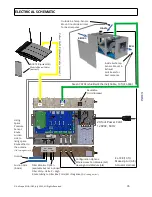
= Motor 2 header, this header is where the Supply Valve Control Wires are
connected. NOTE: polarity P23-1 = ground (-), P23-3 = positive (+)
P1
= MUA header, this header is where the actuator for the AIS Module that brings in
Outside Make-Up Air is wired to. The
JP3
jumper must be shunted to supply 24VDC to
the actuator.
P2
= Heat Assist header, this header is where the actuator for the AIS Module that
brings in Hot Attic Air is wired to. The
JP4
jumper must be shunted to supply 24VDC to the actuator.
P3
= WHF header, this header is where the actuator for the AIS Module that allows Hot Living Space Air into
the Attic (ventilation cooling) is wired to. The
JP5
jumper must be shunted to supply 24VDC to the actuator.
P5
= InterLock header, this header is where the FIRE InterLock and HOOD InterLock are wired to.
It is important that
no voltage
be sent to the board from external sources.
FIRE-INTERLOCK: P5-1 = High (+) P5-2 = ground (-) circuit to be closed to activate
HOOD INTERLOCK: P5-3 = High (+) P5-4 = ground (-) circuit to be closed to activate
Note: the grounds are used by the Actuator harnesses just add your circuit wire to it.
Fire Interlock:
This allows you to disable operation of the unit when a fire alarm is triggered.
This will override ALL other active MUA modes. While triggered, this interlock disables the fan and sets the
damper doors to the Off position. Removal of the interlock allows the unit to resume. It is important that
no voltage
be sent to the board from external sources when choosing how to wire this interlock. It is
designed to operate only as a closed loop circuit.
Hood Interlock:
This allows you to FORCE Enable Make-up Air when an Appliance such as the Kitchen Hood is activated.
This will override ALL other active MUA modes EXCEPT the Fire Interlock.
It is important that
no voltage
be sent to the board from external sources when choosing how to wire this
interlock. It is designed to operate only as a closed loop circuit. This interlock is triggered by closing the
circuit between two contacts on the board.
If you wish to only turn on the MUA when a certain appliance is active but you still want to use the other
modes available. Than this can be accomplished by turning the Make-Up Air slide button (in the MUA
interface) to “OFF” and wiring the HOOD Interlock to be closed when that appliance is turned on. This will
keep Make-Up Air “OFF”, regardless of the pressure in the living space, and allows you to operate other
Modes. Yet the Make-Up Air Unit will activate (and override all other active modes) and bring in outside air
when the appliance is turned on.
The exact method of closing this circuit will depend on the particular installation and equipment the
controller interlock is interfacing with. One possible way of doing so is with a double-pole wall switch, in
which it it wired so that one pole is used to control power to the appliance and the other pole
(DISCONNECTED) closes the interlock contacts. Another way would be to use a relay or current switch that
is activated when the appliance is turned on. It is also possible to use switch like devices that close a switch
when certain conditions are met like an AccuStat (LH1) AS LONG AS NO VOLTAGE IS SENT TO THE BOARD.
More modern devices like Wifi Smart Controllers can also be used to activate both appliance and MUA with
an App.
NOTE: the
reset
button on the board next to the power jack.
© AirScape MUA-IOM, July 2022, All Rights Reserved.
25
P5-1, 2, 3, 4


