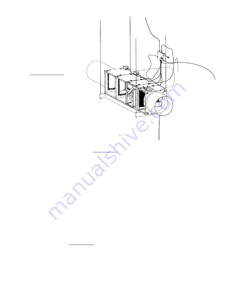
A
- Route and connect the Green
Cat5 Cable from the MUA CP Fan
Jack to the Fan Box on the unit
B
- Route and connect the actuator
wires from the MUA CP (bottom) to
the actuators on the selector
box(es)
ACTUATOR 1 = MUA
ACTUATOR 2 = HEAT ASSIST
ACTUATOR 3 = WHOLE HOUSE FAN
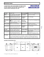
(see
)
C
- Route and connect a Cat5 Cable
(not incl.) from the MUA CP Web
Jack to the router of your network
D
- Route and Install the (OAT)
Outside Air Temp sensor in the
outside air inlet.
E
- Route and Install the (IAT) Inside
Air Temperature sensor close to the
Fan (return) inside the Duct and seal
around the wiring.
(AAT) Place the Attic Temperature in
a safe place in the Attic (if
purchased).
F
- Plug the 20 ft fan and10 ft controller power cords into a ground tested socket.
G
- OTHER CONNECTIONS, see details in
(depends on building codes)
FIRE ALARM: Fire Interlock, if triggered (connects P5-1 to P5-2), all dampers to default, Fan OFF, Overrides
all other modes (Safety Interlock).
KITCHEN HOOD: Hood Interlock, if triggered (connect P5-3 to P5-4) Force Enable Make-up Air mode,
maintains at least min speed, Overrides all other modes EXCEPT Fire Interlock.
HOT WATER HEAT: The Hot Water Flow Control to the Coil Box is established through a 0 - 10VDC Control
Signal, connect to P23-3 and P23-1(Control Signal Only)
Note: Control Signal Wires can be routed through the Control Panel Box wall knock-out or open hole, using
provided strain relief and adapter.
H
– Route 1/8” I.D. tubing (not incl.) from the controller pressure sensor to the outside.
I
– Route 1/8” I.D. tubing (not incl.) from the controller pressure sensor to the living space.
J
– Route two 1/8” I.D. tubing (not incl.) from the controller filter pressure sensor to filter module
(if purchased).
Controls:
The Make-Up Air Unit's controls can be accessed through a webpage, which means the Control Box must
be wired to a network, see
© AirScape MUA-IOM, July 2022, All Rights Reserved.
19
B
B
C
E
A
D
G
FF
F
E
X
H
I
J


