Replace the lid and tighten the screws
In order to activate and control the Differential Pressure Sensor, added ability has to be unlocked in the
controller. This is done via a web browser on any computer, tablet or smartphone that is connected to the
same Local Area Network (LAN) as the MUA unit. Make sure the MUA unit is on and connected to the
network router via Cat-5 cable. Open a web browser on any device that is connected to the same network
as the MUA unit. In the URL Address Bar of the browser, type in the IP Address of the MUA Unit and allow
the window to load. (See
and it’s “tip” if it does not work)
If the page loads and the MUA interface is up enter the
address bar and at the end of the IP address add
/config and press enter. Like: 192.168.10.3
/config
The Factory Settings page should now be up.
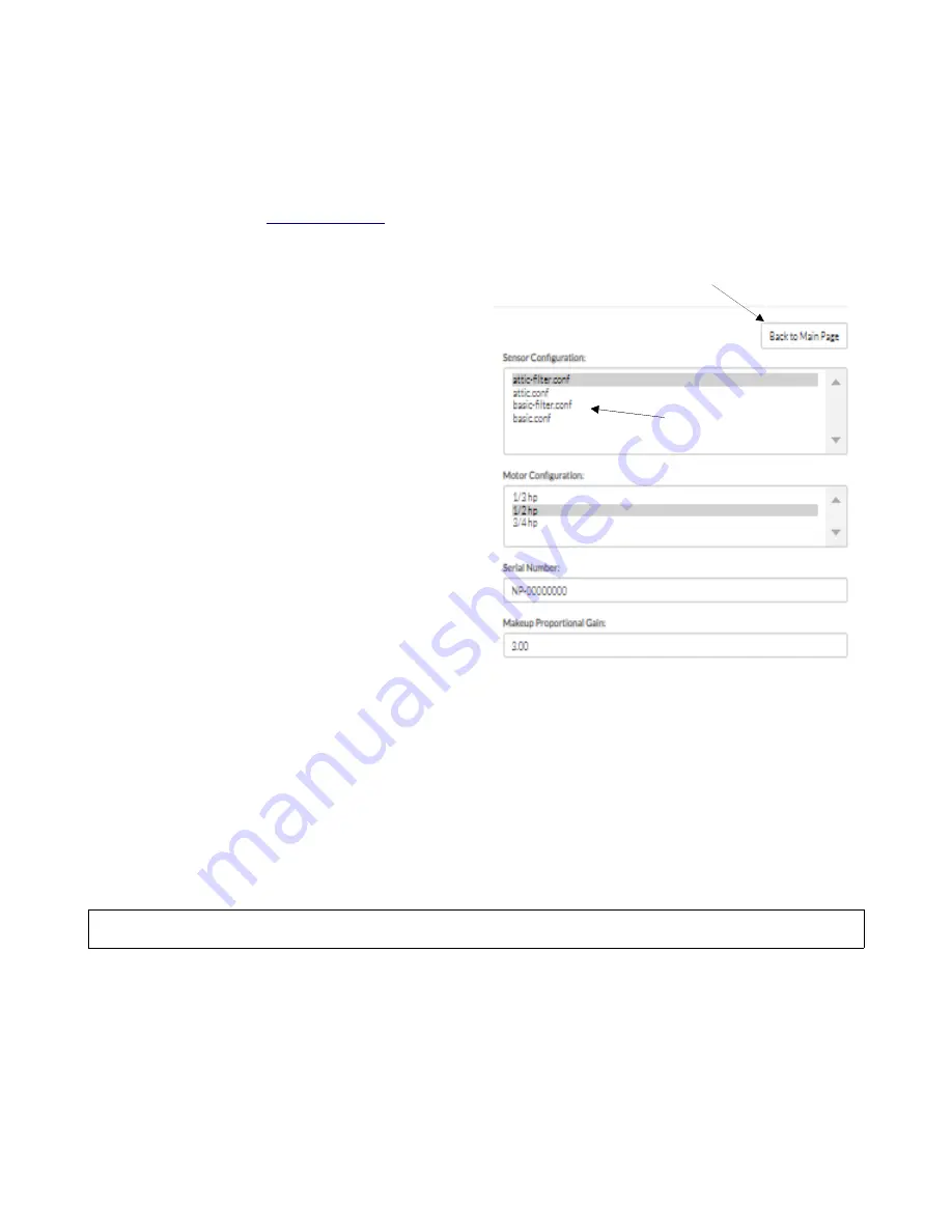
On the right hand top of the page there is a box with 4
sensor configuration options. (see image)
If you purchased the
standard MUA
unit select
“basic-filter.conf”
If you purchased the
Heating Assist MUA
unit select
“attic-filter.conf”
Click the “Submit” Button at the bottom of the page.
this completes the activation of the Differential
Pressure Sensor Option.
Go back to the main MUA unit page by clicking on the
“Back to Main Page” button (RH Top see image).
You can also click in the IP Address in the URL Address Bar and by simply deleting the /config portion of the
address and by pressing Enter you reactivate the main interface.
It furthermore requires 1/8” I.D. Vinyl tubing to connect the two sensor ports to the filter module’s two
static ports (2 x tubing, which is not included).
Looking at the static ports (on the back of the filter box) connect the lowest (closest to the fan) static port
with the RH sensor port in the controller. (negative pressure side) Connect the other port to the LH sensor
port on the controller for negative pressure indications of the filter status (this can be reversed if desired).
INSTALLATION OF WIRING AND CONTROL
Most of the wiring connections to the MUA Unit are made at the fan-mounted electrical box and at the
controller, however the controller needs to be (hard)wired to the wireless router in your network.
The main connections are a 20 ft, black, factory-installed power cord on the fans electrical box and a 10 ft
power cord for the controller need to be plugged into a ground tested receptacle. The supplied green Cat5
Ethernet cable connects the controller fan port to the fan’s RJ45 Jack. Depending on the configuration of
MUA you purchase upto three molex harnesses need to be connected to the actuators of the correct AIS
modules. See below.
© AirScape MUA-IOM, July 2022, All Rights Reserved.
18
Filter
Configuration
options
Return to
MUA Control Tab


