AirLive PoE-FSH2442 User’s Manual
8
Chapter 5: UNDERSTANDING LED INDICATORS
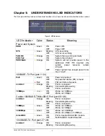
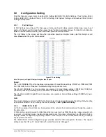
The front panel LEDs provides instant status feedback, and, helps monitor and troubleshoot when needed.
Figure 6. LED indicators
LED Indicator
Color Status
Meaning
Power and System
PWR
●
Green
ON
OFF
Power ON
Power OFF
SYS
●
Green
Blinking
OFF
CPU is working
CPU is not working
FAN OK
FAN Fail
●
Orange
ON
ON
System fan is working normally
System fan is failed
PWR MAX.
●
Orange
ON
OFF
System will not provide power to the
additional POE PD inserted (the
system power resource remain
≤
15.4W)
Power system has enough power more
then 15.4W
100BASE-TX Port (port 1~24)
PoE
●
Green
●
Red
ON
OFF
ON
Power is provided
No powered device (PD) is found
PoE port failure happens
Link/Act
●
Orange
ON
Blinking
OFF
Port is connected
Transmitting/Receiving
Port is connected
100Mbps
●
Green
ON
OFF
Works on 100Mbps
Works on 10Mbps
Combo 1000BASE-T/Mini-GBIC Port (port 25~26)
Link/Act
●
Orange
ON
Blinking
OFF
Port is connected
Transmitting/Receiving
Port is connected
100Mbps
●
Green
ON
OFF
Works on 100Mbps
Works on 10Mbps
1000Mbps
●
Green
ON
OFF
Works on 1000Mbps
Works on 10Mbps or 100Mbps
mini-GBIC
●
Green
ON
OFF
Port is inserted Mini-GBIC module
No Mini-GBIC module inserted
1000BASE-TX Port (port 27~28)
Link/Act
●
Orange
ON
Blinking
Port is connected
Transmitting/Receiving


