


Chapter 4 BMC Configuration and Setting
J4076-01 User's Manual
80
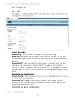
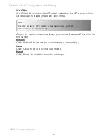
UTC Offset
UTC Offset list contains the UTC offset values for the NTP server, which
can be used to display the exact local time.
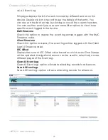
Check this option to automatically synchronize Date and Time with the
NTP Server.
Refresh
Click ‘Refresh’ to reload the current date & time settings.
Save
Click ‘Save’ to save any changes made.
Reset
Click ‘Reset’ to reset the modified changes.
note :
Use the correct UTC offset after adjusting for DST.
Automatically synchronize
Содержание J4076-01
Страница 1: ...J4076 01 SAS SATA JBOD User s Manual UM_J4076 01_v6 1_082417...
Страница 3: ...contents 4 9 Firmware safety mode 99 Chapter 5 Technical Support 104...
Страница 104: ...J4076 01 User s Manual 97 Chapter 4 BMC Configuration and Setting 5 Processing 6 Update successful...
Страница 107: ...Chapter 4 BMC Configuration and Setting J4076 01 User s Manual 100...


