50
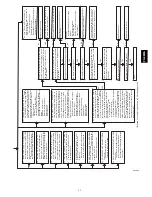
Is LED status light on?
Is LED status light b
linking rapidly without a
pause?
Is LED status light b
linking ON/OFF slo
w
ly
with a combination of shor
t and long
flashes?
Deter
m
ine status code
.
The status code is
a
2 digit number with the first digit deter
m
ined
by
t
h
e
number of
shor
t
flashes
and
the
second
digit b
y
the number of long flashes?
Go to section belo
w f
o
r the status code that
w
a
s flashed.
Is there 115V at L1 and L2?
Is there 24V at SEC-1 and SEC-2?
Replace fur
nace control.
Chec
k f
o
r correct line v
o
ltage polarity
. If units
are twinned, chec
k f
o
r proper lo
w-v
oltage
(24V) transf
o
rm
er phasing.
To
recall status code briefly rem
o
v
e
and reconnect one RED wire from the draft
saf
e
guard s
witch to displa
y stored status code
. On RED LED control do not
remo
v
e
po
wer or b
lo
wer access panel bef
ore initiating status code recall.
Y
o
u
can also recall the pre
vious
status
code b
y
momentar
ily
shor
ting the
TEST/TWIN
ter
m
inal to Com24V ter
m
inal until the LED goes out.
LED will flash the status
code of the pre
v
ious f
ault or status code #11 (1 shor
t and 1 long flash) if there
w
a
s no pre
v
ious f
a
ult.
After the control repeats the code 4 times
, the control
will
go through a brief component test sequence
.
The
inducer will star
t and
ru
n
fo
r the entire component test.
The
HSI,
b
lo
w
er motor F
A
N speed (AMBER LE
D
boards only) HEA
T
speed, and COOL speed will r
u
n f
o
r 10 – 15 seconds each.
Gas v
alv
e and humidifier will not be tur
ned on.
W
a
s there a pre
v
ious status code
other than #11?
Is door s
w
itch closed?
Is there 115V going to s
w
itch?
Replace door s
w
itch.
Replace transf
or
mer
.
Does the control respond to
W
, Y1 (if present),
Y/Y2, and G (24V) ther
mostat signals?
Run system through
a heating or cooling cycle
to chec
k operation.
Status codes are erased
after 72 hours
. On RED LED boards stored
status codes can also be erased whene
v
er
(115V or 24V) is interr
u
pted.
Replace fur
n
ace control.
Is door s
w
itch closed?
Is circuit break
er closed?
Chec
k f
o
r continuity
in wire from circuit break
e
r
to fur
n
ace
.
Close circuit break
er and go bac
k to ST
AR
T
.
Chec
k room ther
mostat or
interconnecting cab
le
.
Is 24V present at
W
,
Y1 (if present),
Y/Y2 or
G ther
mostat ter
m
inals on the fur
n
ace control?
Disconnect all the ther
mostat wires from the
fur
n
ace control.
Does the prob
lem repeat when using
a jumper wire?
The ther
mostat is not compatib
le with the
fur
nace
control.
Either install a ballast resistor
,
connect the Com24V ther
mostat ter
m
inal to
the ther
mostat, or replace the ther
mostat.
NO
YES
YES
NO
NO
YES
YES
YES
YES
NO
YES
YES
NO
YES
NO
YES
NO
NO
NO
YES
NO
YES
NO
ST
AR
T
NO
A02106A
Fig. 55 -- Troubleshooting Guide
PG
8M
EA
Содержание PG8JEA
Страница 4: ...4 A10269 Fig 2 Clearances to Combustibles PG8MEA ...
Страница 28: ...28 A10133 Fig 33 Chimney Inspection Chart PG8MEA ...
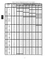
Страница 38: ...38 Table 13 Orifice Size and Manifold Pressure In W C for Gas Input Rate A10180 PG8MEA ...
Страница 39: ...39 Table 13 Orifice Size and Manifold Pressure In W C for Gas Input Rate CONT A10180A PG8MEA ...
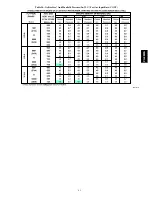
Страница 40: ...40 Table 14 Orifice Size And Manifold Pressure In W C For Gas Input Rate A10181 PG8MEA ...
Страница 41: ...41 Table 14 Orifice Size And Manifold Pressure In W C For Gas Input Rate CONT A10181A PG8MEA ...
Страница 49: ...49 A08176 Fig 54 Wiring Diagram PG8MEA ...

