


46
NOTE
: The materials needed in item 9 can usually be purchased
at local hardware stores.
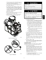
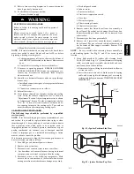
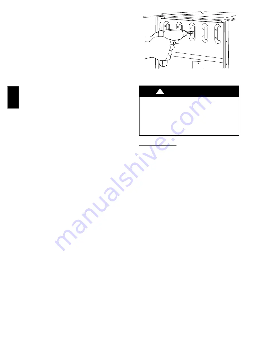
(1.) Attach variable--speed, reversible drill to the end of
spring cable (end opposite brush).
(2.) Insert brush end of cable into the outlet opening of
cell and slowly rotate with drill. DO NOT force
cable. Gradually insert cable into upper pass of cell.
(See Fig. 53 .)
(3.) Work cable in and out of cell 3 or 4 times to obtain
sufficient cleaning. DO NOT pull cable with great
force. Reverse drill and gradually work cable out.
(4.) Insert brush end of cable in burner inlet opening of
cell, and proceed to clean 2 lower passes of cell in
same manner as upper pass.
(5.) Repeat foregoing procedures until each cell in fur-
nace has been cleaned.
(6.) Using vacuum cleaner, remove residue from each
cell.
(7.) Using vacuum cleaner with soft brush attachment,
clean burner assembly.
(8.) Clean flame sensor with fine steel wool.
(9.) Install NOx baffles (if removed).
(10.) Reinstall burner assembly. Center burners in cell
openings.
10. Remove old sealant from cell panel and collector box
flange.
11. Spray releasing agent on the heat exchanger cell panel
where collector box assembly contacts cell panel.
NOTE
: A releasing agent such as cooking spray or equivalent
(must not contain corn or canola oil, aromatic or halogenated
hydrocarbons or inadequate seal may occur) and RTV sealant
(G.E. 162, 6702, or Dow--Corning 738) are needed before
starting installation. DO NOT substitute any other type of RTV
sealant. G.E. 162 (P771--9003) is available through RCD in 3--oz.
tubes.
12. Apply new sealant to flange of collector box and attach to
cell panel using existing screws, making sure all screws
are secure.
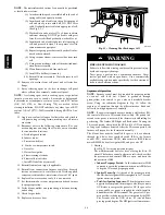
13. Reconnect wires to the following components. (Use con-
nection diagram on wiring label, if wires were not marked
for reconnection locations.):
a. Draft safeguard switch.
b. Inducer motor.
c. Pressure switch(es).
d. Limit over--temperature switch.
e. Gas valve.
f. Hot surface igniter.
g. Flame--sensing electrode.
h. Flame rollout switches.
i. Install NOx baffles (if removed).
14. Reinstall internal vent pipe, if applicable.
15. Reinstall vent connector on furnace vent elbow. Securely
fasten vent connector to vent elbow with 2 field--supplied,
corrosion--resistant, sheet metal screws located 180
_
apart.
16. Replace blower access door only, if it was removed.
17. Set thermostat above room temperature and check furnace
for proper operation.
18. Verify blower airflow and speed changes between heating
and cooling.
19. Check for gas leaks.
20. Replace outer access door.
A91252
Fig. 53 -- Cleaning Heat Exchanger Cell
FIRE OR EXPLOSION HAZARD
Failure to follow this warning could result in personal injury,
death and/or property damage.
Never purge a gas line into a combustion chamber. Never
test for gas leaks with an open flame. Use a commercially
available soap solution made specifically for the detection of
leaks to check all connections.
!
WARNING
Sequence of Operation
NOTE
: Furnace control must be grounded for proper operation
or control will lock out. Control is grounded through
green/yellow wire routed to gas valve and manifold bracket
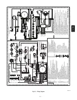
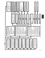
screw. Using the schematic diagram in Fig. 54, follow the
sequence of operation through the different modes. Read and
follow the wiring diagram very carefully.
NOTE
: If a power interruption occurs during a call for heat (W),
the control will start a 90--second blower--only ON period two
seconds after power is restored, if the thermostat is still calling for
gas heating. The Amber LED light will flash code 12 during the
90--second period, after which the LED will be ON continuous,
as long as no faults are detected. After the 90--second period, the
furnace will respond to the thermostat normally.
The blower door must be installed for power to be conducted
through the blower door interlock switch ILK to the furnace
control CPU, transformer TRAN, inducer motor IDM, blower
motor BLWM, hot--surface igniter HSI, and gas valve GV.
1. Heating
(See Fig. 25 for thermostat connections.)
The wall thermostat “calls for heat,” closing the R--to--W
circuit. The furnace control performs a self--check, verifies
the pressure switch contacts PRS are open, and starts the
inducer motor IDM.
a.
Inducer Prepurge Period
-- As the inducer motor IDM
comes up to speed, the pressure switch contacts PRS close
to begin a 15--second prepurge period.
b.
Igniter Warm--Up
-- At the end of the prepurge period,
the Hot--Surface igniter HSI is energized for a 17--second
igniter warm--up period.
c.
Trial--for--Ignition Sequence
-- When the igniter warm--
up period is completed, the main gas valve relay contacts
GVR close to energize the gas valve GV, the gas valve
opens, and 24 vac power is supplied for a field--installed
humidifier at the HUM terminal. The gas valve GV per-
mits gas flow to the burners where it is ignited by the HSI.
Five seconds after the GVR closes, a 2--second flame
proving period begins. The HSI igniter will remain ener-
PG
8M
EA
Содержание PG8JEA
Страница 4: ...4 A10269 Fig 2 Clearances to Combustibles PG8MEA ...
Страница 28: ...28 A10133 Fig 33 Chimney Inspection Chart PG8MEA ...
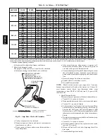
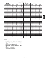
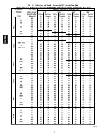
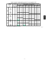
Страница 38: ...38 Table 13 Orifice Size and Manifold Pressure In W C for Gas Input Rate A10180 PG8MEA ...
Страница 39: ...39 Table 13 Orifice Size and Manifold Pressure In W C for Gas Input Rate CONT A10180A PG8MEA ...
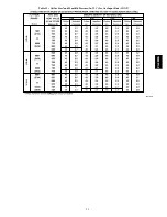
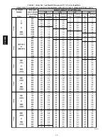
Страница 40: ...40 Table 14 Orifice Size And Manifold Pressure In W C For Gas Input Rate A10181 PG8MEA ...
Страница 41: ...41 Table 14 Orifice Size And Manifold Pressure In W C For Gas Input Rate CONT A10181A PG8MEA ...
Страница 49: ...49 A08176 Fig 54 Wiring Diagram PG8MEA ...


