


NA (Network Analyzer) Mode
47
o
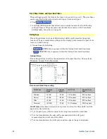
Ref Position
Manually set the position of the reference line. Values must be
between 0 (TOP line) and 10 (BOTTOM line)
Scale annotation on the
FieldFox screen
· Reference Line = red arrow
·
Ref Level
= –40 dB
·
Ref Position
= 1
·
Scale
= 2 dB per division
Electrical Delay
Electrical delay is a mathematical function that simulates
a variable length of
lossless transmission line. Use the electrical delay feature to compensate for the
linear phase shift through a device and view only the deviation from linear phase
of the device.
You can set the electrical delay independently for each measurement trace. To
apply an electrical delay to all measurement traces, use Port Extensions. Learn
how on page 52.
Learn how to set Phase formats on page 44.
How to set Electrical Delay
Press
Scale / Amptd
Then
More
Then
Electrical Delay
Enter a time value using the numeric keypad, the
▲|▼
arrows, or the rotary
knob.
Press a multiplier key. Learn about multiplier abbreviations on page 19.
Electrical Delay can also be set using the
Mkr->Delay
feature. Learn how on page
Phase Offset
Phase offset mathematically adjusts the phase measurement by a specified
amount, up to 360°. Use this feature in the following ways:
Improve the display of a phase measurement.
This is similar to the way you
would change the reference level in an amplitude measurement. Change the
phase response to center or align the response on the screen.
Emulate a projected phase shift in your measurement.
For example, if you
know that you need to add a cable and that the length of that cable will add a
certain phase shift to your measurement, you can use phase offset to add that
amount and simulate the complete device measurement.
You can set the phase offset independently for each measurement trace.
How to set Phase Offset
Press
Scale / Amptd


