


22
FieldFox User’s Guide
o
Insertion Loss (2-Port)
2-port transmission measurement that accurately
displays the loss through a cable or other device in dB. Both ends of the
cable must be connected to the FieldFox. NO phase information is included
in this measurement. Learn more on page 29. This feature is available only
with an option on some FieldFox models. For detailed information, please
view the FieldFox Configuration Guide at:
http://cp.literature.agilent.com/litweb/pdf/5990-9836EN.pdf
o
DTF (Lin)
Distance to Fault in Linear format.
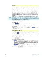
Quick Settings Table
Both CAT and NA Modes allow you to view and change most relevant settings
from a single location. All of these settings are discussed in this chapter and,
unless otherwise noted, ALL of these settings can also be made using the
standard softkey menus.
How to view and change Quick Settings
Press
Meas Setup 4
.
Then
Settings
.
Press
Next Page
and
Previous Page
to view all settings. If these softkeys are
NOT available, then all available settings fit on one page.
To change a setting:
o
Use the
▲|▼
arrows to highlight a setting.
o
Then press
Edit
. The current setting changes to
yellow.
o
Some settings require you to press a softkey to change the value. Otherwise,
use the numeric keypad,
▲|▼
arrows, or rotary knob to change the value.
o
When finished changing a value, press
Done Edit
.
Press
Dock Window
to relocate the Settings table to a position relative to the
trace window. The Dock Window setting persists through a Preset. Choose
from the following:
o
Full (Default setting)
Only the Settings table is shown on the screen. The
trace window is temporarily not shown.
o
Left
The Settings table is shown to the left of the trace window.
o
Bottom
The Settings table is shown below the trace window.
When finished changing ALL settings, press
Done
to save your settings.
Frequency Range
Set the range of frequencies over which you would like to make CAT Mode
measurements.
When the frequency range is changed after a calibration is performed, the cal
becomes interpolated. Learn more on page 77.
How to set Frequency Range
Press
Freq/Dist
.


