


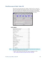


Pulse Measurements Mode - Option 330
161
Then choose from the following:
o
Freerun
The USB Power Sensor acquires data without waiting for a trigger.
This mode is NOT supported for Trace Graph measurements.
o
Internal
The USB Power Sensor acquires data when a valid pulse signal is
detected at the RF input. The following Trigger settings determine the
validity of the trigger signal.
o
External
The USB Power Sensor acquires data when a valid
TTL signal is
detected at the USB Power Sensor external trigger input.
Trigger Edge
This setting determines which edge of a trigger signal initiates data acquisition.
Press
Sweep 3
Then
Trigger
Then
Trig Edge
Then choose from the following:
o
Pos
Acquisition is triggered by the rising (positive) edge of a valid signal.
o
Neg
Acquisition is triggered by the falling (negative) edge of a valid signal.
Trigger Delay
After a valid trigger signal is received at the USB Power Sensor, data acquisition
begins after the specified Trigger Delay time
PLUS
the specified Start time. See
the Pulse Timing diagram on page 162 for more information.
Press
Sweep 3
Then
Trigger
Then
Trig Delay
Then enter a value using the numeric keypad, the
▲|▼
arrows, or the rotary
knob.
Auto Trigger
Used ONLY when Trigger Type = Internal, this setting determines whether the
trigger level is set manually or is set to the default level in the USB Power Sensor
firmware.
Press
Sweep 3
Then
Trigger
Then
AutoTrig
Then choose from the following:
o
ON
Trigger level is determined by the USB Power Sensor firmware.
o
OFF
The trigger level is set manually using the Trigger Level setting.
Trigger Level
Used when Trigger Type = Internal AND Auto Trigger = OFF (Manual).
Press
Sweep 3


