


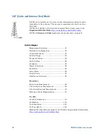


CAT (Cable and Antenna Test) Mode
29
A 2-port Insertion Loss measurement is usually more accurate than a 1-port
Cable Loss measurement. However, to perform a 2-port Insertion Loss
measurement, both ends of the cable must be connected to the FieldFox, and the
FieldFox must have option 110 installed.
NOTE
In high-loss conditions, a Cable Loss measurement becomes ‘noisy’ as the test
signal becomes indistinguishable in the FieldFox noise floor. This can occur
when measuring a very long cable and using relatively high measurement
frequencies. To help with this condition, use High Power (page 27), and
Averaging. (page 25).
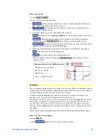
How to make a 1-port Cable Loss Measurement
1. Press
Preset
then
Preset
.
2. Then
More
then
Cable Loss (1-Port)
.
3. Connect the cable to be tested.
4. Press
Freq/Dist
and enter
Start
and
Stop
frequency values of the
measurement.
5. Press
Sweep 3
then
Min Swp Time
. Increase the Sweep Time until a stable
trace is visible on the screen. The amount of time that is required increases
with longer cable lengths. Learn more in the
Supplemental Online Help:
www.agilent.com/find/fieldsfoxsupport
6. Remove the cable to be tested.
7. Press
Cal 5
, then
QuickCal
or
OSL
.
8. Follow the prompts to perform calibration at the end of the jumper cable or
adapter. Learn more about Calibration on page 62.
9. Connect the cable to be tested.
NOTE
Low-level standing waves (also also known as ‘ripple’) which may be visible in
reflection measurements, can hide the actual loss of the cable. Steps 10 through
13 can minimize the ripple. Perform the measurement with and without steps 10
through 13 and choose the method with the least amount of ripple.
10. Connect a LOAD at the end of the cable to be tested. This limits the
reflections to faults that are located in the cable under test.
11. Press
Trace 6
then
Data->Mem
to store the trace into Memory.
12. Remove the LOAD and leave the end of the cable to be tested open.
13. Press
Data Math
then
Data
–
Mem
. The ripple in the measurement is
removed. These minor imperfections in the cable should not be considered in
the Cable Loss measurement.
14. Use Averaging to remove random noise from high-loss measurements. Press
BW 2
then
Average
.
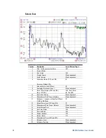
The displayed trace shows the Cable Loss values in one direction through the
cable. A Return Loss measurement would show the loss for both down the cable
and back. Therefore, a Cable Loss measurement is the same as a Return Loss
measurement divided by 2.
The average Cable Loss across the specified frequency range is shown on the
screen below the graticules.
Содержание FieldFox N9912A
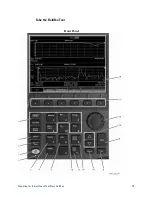
Страница 15: ...Preparing for Initial Use of Your New FieldFox 15 Take the FieldFox Tour Front Panel ...
Страница 134: ...134 N9912A FieldFox User s Guide RF Out and RF In test port cables attached to form a Thru connection ...
Страница 194: ...194 N9912A FieldFox User s Guide Batteries Safe Handling and Disposal ...
Страница 195: ...Safety Considerations 195 Inspired Energy Battery ...
Страница 196: ...196 N9912A FieldFox User s Guide ...
Страница 197: ...Safety Considerations 197 ...
Страница 198: ...198 N9912A FieldFox User s Guide ...


