


78
Chapter 4
Replacement Procedure
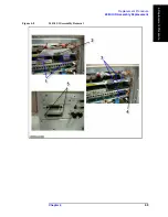
A1 Source Module Replacement
A1 Source Module Replacement
Tools Required
•
torque screwdriver, T15 and T20
•
torque screwdriver, T10 (set to 9 in-lb)
•
open torque wrench, 5/16 inch
•
flat edge screwdriver
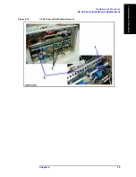
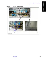
Removal Procedure
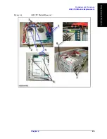
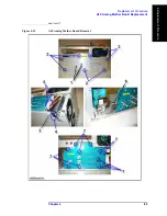
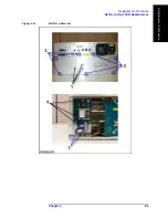
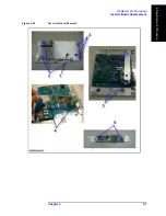
Refer to Figure 4-13 for this procedure.
Step 1.
Remove the Outer Cover as described in “Outer Cover Replacement” on page 54.
Step 2.
Remove the Front Panel as described in “Front Panel Replacement” on page 56.
Step 3.
Remove the A2 Receiver Module as described in “A2 Receiver Module Replacement” on
page 74.
Step 4.
Disconnect the four RF cable connectors (item 1) from the A1 Source Module and the A9
LF Source Bias Module.
Step 5.
Remove the two TORX T10 screws (item 2) fastening the A1 Source Module.
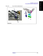
Step 6.
Slide forward the A1 Source Module.
Step 7.
Remove the four TORX T10 screws (item 3) fastening bracket and angle for the A1 Source
Module.
Replacement Procedure
Step 1.
Reverse the order of the removal procedure.
NOTE
Set a torque to 9 in-lb for torque driver when fasten the TORX T10 screws (item 2, and
item 3).
Содержание E5061B
Страница 1: ... Established 1981 Advanced Test Equipment Rentals www atecorp com 800 404 ATEC 2832 ...
Страница 51: ...50 Chapter3 Replaceable Parts Replaceable Parts List ...
Страница 100: ...Chapter 4 99 Replacement Procedure Front Frame Replacement 4 Replacement Procedure Figure 4 24 Front Frame Removal ...
Страница 103: ...102 Chapter4 Replacement Procedure Handle Assembly Replacement ...
Страница 116: ...115 E Power Requirement D Power Requirement ...
Страница 118: ...Appendix D 117 Power Requirement Preparation for Power Supply E Power Requirement Figure D 1 Power cable options ...
Страница 123: ...122 AppendixE Messages ...


