42
2
Overview of Remote Control
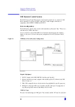
USB Remote Control System
1. Registering Alias When USB Cable Is Connected
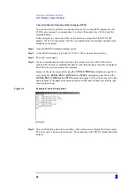
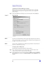
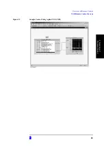
When new device is connected via USB cable, the following dialog box will appear
automatically.Follow the steps below to register alias, when you use the Agilent I/O
Libraries Suite 14.
Step 1.
In the Assign USB device alias dialog box, enter an alias and the click the
OK
button.
Figure 2-7
Registering Alias
NOTE
For alias, use the ASCII format less than 127 digits.Alias is upper/lower case insensitive.
If "Never show this dialog" is selected in the "Show this dialog" frame, the dialog box does
not appear even if a new device is connected.
NOTE
Once new device is identified, the "New Hardware Search Wizard" will start.Follow the
instruction to implement the processing.
2. Changing Alias on Setting Screen
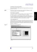
The following are steps using the Agilent I/O Libraries Suite 14.
Step 1.
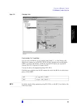
Step 1: From the Start menu of your PC, click Program - Agilent IO Libraries Suite
-Agilent Connection Expert to open the Config setting screen.
Step 2.
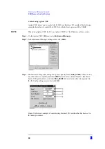
In the Config setting screen, select the alias names from
USB0
onward in the
Instrument
I/O on this PC
frame, and then use the
Change Properties
from
I/O Configuration
on the
menu bar.
Содержание E5052A
Страница 4: ...4 ...
Страница 28: ...28 1 Making Effective Use of This Manual How to Use This Manual ...
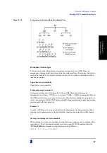
Страница 51: ...3 51 Making a Measurement Trigger System 3 Making a Measurement Figure 3 1 Trigger system ...
Страница 58: ...58 3 Making a Measurement Waiting for End of measurement ...
Страница 76: ...76 4 Reading Writing Measurement Data Entering Data in a Trace ...
Страница 82: ...82 Chapter5 Saving and Recalling File Management Managing Files ...
Страница 476: ...476 AppendixB Status Reporting System Status Register Structure Figure B 3 Status register structure 1 of 6 ...
Страница 478: ...478 AppendixB Status Reporting System Status Register Structure Figure B 5 Status register structure 3 of 6 ...
Страница 480: ...480 AppendixB Status Reporting System Status Register Structure Figure B 7 Status register structure 5 of 6 ...


