


A Look at
aurora
Duet
Issue 2 - 05/00
3 - 5
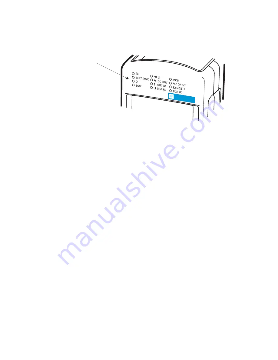
LED indicators
LED
Indicator
Array
aurora
Duet
aurora
Duet
There are eleven Light Emitting Diode (LED) status
indicators grouped on the front face of BRI
aurora
Duet
and
twelve on the PRI
aurora
Duet
.
White text next to an LED relates to Basic Rate
operation on the S interface, orange text relates to Basic
Rate operation on the U interface and blue text relates to
Primary Rate operation.
The LEDs have the following labels, colors and
functions:
TE
Green
shows the unit is operating in TE mode
on the S or U interface.
NT LT Green
shows the unit is operating in NT mode
on the S interface or LT mode on the U
interface.
MON
Green
shows the unit is operating in monitor
mode.
BERT SYNC
Green
shows a BER test is running and pattern
synchronization has been achieved on the data
call in progress.
Содержание aurora Duet
Страница 2: ...auroraDuet Basic Primary Rate ISDN Tester User Guide 428856...
Страница 4: ...auroraDuet Basic Primary Rate ISDN Tester User Guide ii 428856...
Страница 14: ...xii 428856 aurora Duet Basic Primary Rate ISDN Tester User Guide...
Страница 26: ...aurora Duet Basic Primary Rate ISDN Tester User Guide 1 12 428856...
Страница 32: ...2 6 428856 auroraDuet Basic Primary Rate ISDN Tester User Guide...
Страница 44: ...auroraDuet Basic Primary Rate ISDN Tester User Guide 3 12 428856...
Страница 96: ...5 30 428856 auroraDuet Basic Primary Rate ISDN Tester User Guide...
Страница 97: ...Setting Up auroraDuet Issue 2 05 00 5 31...
Страница 98: ...5 32 428856 auroraDuet Basic Primary Rate ISDN Tester User Guide...
Страница 145: ...Monitor Capture Review Functions Issue 2 05 00 7 23...
Страница 166: ...8 18 428856 auroraDuet Basic Primary Rate ISDN Tester User Guide...
Страница 202: ...auroraDuet Basic Primary Rate ISDN Tester User Guide 10 26 428856...
Страница 203: ...Menutree Diagrams Issue 2 05 00 A1 1 Menutree Diagrams A1...
Страница 204: ...A1 2 428856 auroraDuet Basic Primary Rate ISDN Tester User Guide...
Страница 205: ...Menutree Diagrams Issue 2 05 00 A1 3...
Страница 206: ...A1 4 428856 auroraDuet Basic Primary Rate ISDN Tester User Guide...
Страница 214: ...A2 8 428856 auroraDuet Basic Primary Rate ISDN Tester User Guide...
Страница 220: ...A3 6 428856 auroraDuet Basic Primary Rate ISDN Tester User Guide...
Страница 236: ...auroraDuet Basic Primary Rate ISDN Tester User Guide Index 6 428856...


