Agilent Technologies Agilent 86120B Скачать руководство пользователя страница 235

7-5

Specifications and Regulatory Information

Definition of Terms

Measurement 
Cycle Time 

Measurement cycle time

 refers to the cycle time when measuring wavelength 

and power of laser lines. Specific advanced applications may require longer 
cycle times.

Содержание Agilent 86120B

Страница 1: ...Agilent 86120B Multi Wavelength Meter User s Guide ...

Страница 2: ...to defects resulting from improper or inadequate maintenance by Buyer Buyer supplied software or interfac ing unauthorized modifica tion or misuse operation outside of the environmental specifications for the product or improper site preparation or maintenance No other warranty is expressed or implied Agilent Technologies specifically dis claims the implied warranties of merchantability and fitnes...

Страница 3: ...ilent 86120B instruments with firmware ver sion number 2 0 When first turned on the instrument briefly displays the firmware version These instruments have the added capability of measuring broadband devices and chirped lasers Refer to Measuring broadband devices and chirped lasers on page 2 10 Characterize laser lines easily With the Agilent 86120B you can quickly and easily measure any of the fo...

Страница 4: ...r Program the instrument for automatic measurements The Agilent 86120B offers an extensive set of GPIB programming commands These commands allow you to perform automated measurements on manufac turing production lines and remote sites Chapter 4 Programming and Chap ter 5 Programming Commands provide all the information you ll need to know in order to program the Agilent 86120B Display wavelengths ...

Страница 5: ...s and accessories The Agilent 86120B s front panel INPUT connector is no exception When you use improper cleaning and handling techniques you risk expensive instru ment repairs damaged cables and compromised measurements Before you connect any fiber optic cable to the Agilent 86120B refer to Cleaning Con nections for Accurate Measurements on page 1 13 ...

Страница 6: ... 1 WAR N I N G If this instrument is not used as specified the protection provided by the equipment could be impaired This instrument must be used in a normal condition in which all means for protection are intact only WAR N I N G No operator serviceable parts inside Refer servicing to qualified personnel To prevent electrical shock do not remove covers There is no output laser aperture The Agilen...

Страница 7: ...50V for 100 120V operation and 0 16A 250V for 220 240V operation The use of other fuses or materials is prohibited Verify that the value of the line voltage fuse is correct For 100 120V operation use an IEC 127 5 20 mm 0 315 A 250 V Agilent part number 2110 0449 For 220 240V operation use an IEC 127 5 20 mm 0 16 A 250 V Agilent Technologies part number 2110 0448 C AUT IO N Before switching on this...

Страница 8: ...he three prong ac power cord supplied with this instrument Failure to ensure adequate earth grounding by not using this cord may cause instrument damage C AUT IO N Do not connect ac power until you have verified the line voltage is correct as described in Line Power Requirements on page 1 6 Damage to the equipment could result C AUT IO N This instrument has autoranging line voltage input Be sure t...

Страница 9: ...rvice 1 23 2 Using the Multi Wavelength Meter Displaying Wavelength and Power 2 3 Changing the Units and Measurement Rate 2 13 Defining Laser Line Peaks 2 16 Measuring Laser Separation 2 20 Measuring Modulated Lasers 2 23 Measuring Total Power Greater than 10 dBm 2 25 Calibrating Measurements 2 26 Printing Measurement Results 2 28 3 Measurements Applications Measuring Signal to Noise Ratios 3 3 Me...

Страница 10: ...rement Instruction 5 69 SENSe Subsystem 5 69 STATus Subsystem 5 74 SYSTem Subsystem 5 79 TRIGger Subsystem 5 84 UNIT Subsystem 5 86 6 Performance Tests Test 1 Absolute Wavelength Accuracy 6 3 Test 2 Sensitivity 6 4 Test 3 Polarization Dependence 6 5 Test 4 Optical Input Return Loss 6 6 Test 5 Amplitude Accuracy and Linearity 6 9 7 Specifications and Regulatory Information Definition of Terms 7 3 S...

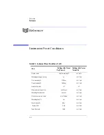
Страница 11: ...Contents 3 Contents Power Cords 8 16 Agilent Technologies Service Offices 8 18 ...

Страница 12: ......

Страница 13: ...6 Step 4 Connect a Printer 1 7 Step 5 Turn on the Agilent 86120B 1 8 Step 6 Enter Your Elevation 1 10 Step 7 Select Medium for Wavelength Values 1 11 Step 8 Turn Off Wavelength Limiting 1 12 Cleaning Connections for Accurate Measurements 1 13 Returning the Instrument for Service 1 23 Getting Started ...

Страница 14: ...outside the cabinet must be less than the maximum operating temperature of the product by 4 C for every 100 watts dissipated in the cabinet If the total power dissipated in the cabinet is greater than 800 watts then forced convection must be used C AUT IO N This product is designed for use in INSTALLATION CATEGORY II and POLLUTION DEGREE 2 per IEC 1010 and 664 respectively C AUT IO N Install the i...

Страница 15: ...carrier and the nearest Agilent Technologies sales and service office Agilent Technologies will arrange for repair or replacement of damaged or incomplete shipments without waiting for a settlement from the transportation company Notify the Agilent Technologies customer engineer of any problems 2 Make sure that the serial number and options listed on the instrument s rear panel label match the ser...

Страница 16: ...tain power cord 1 8120 1703 Option 901 Australia New Zealand China power cord 1 8120 0696 Option 902 European power cord 1 8120 1692 Option 906 Switzerland power cord 1 8120 2296 Option 912 Denmark power cord 1 8120 2957 Option 917 India South Africa power cord 1 8120 4600 Option 918 Japanese power cord 1 8120 4754 Option 919 Israel power cord 1 8120 5181 Option UK5 Protective soft carrying case 1...

Страница 17: ...4 Verify that the value of the line voltage fuse in the pull out drawer is correct The recommended fuse is an IEC 127 5 20 mm 6 3A 250 V Agilent Technologies part number 2110 0703 Notice that an extra fuse is provided in a drawer located on the fuse holder WAR N I N G For continued protection against fire hazard replace line fuse only with same type and ratings type T 6 3A 250V for 100 240V operat...

Страница 18: ...e to ensure adequate earth grounding by not using this cord may cause instrument damage C AUT IO N Do not connect ac power until you have verified the line voltage is correct as described in the following paragraphs Damage to the equipment could result C AUT IO N This instrument has autoranging line voltage input Be sure the supply voltage is within the specified range 1 Verify that the line power...

Страница 19: ...ment also has a right angle connector so that the Agilent 86120B can be used while sitting on its rear feet You can order additional ac power cables for use in different geographic areas Refer to Front Panel Fiber Optic Adapters on page 8 15 Step 4 Connect a Printer The Agilent 86120B can print hardcopies of measurement results on a printer The output is ASCII text If you don t have a printer cont...

Страница 20: ...splay should look similar to the following figure The front panel LINE switch disconnects the mains circuits from the mains sup ply after the EMC filters and before other parts of the instrument 2 If the Agilent 86120B fails to turn on properly consider the following possibilities Is the line fuse good Does the line socket have power Is it plugged into the proper ac power source If the instrument ...

Страница 21: ... the front panel OPTICAL INPUT connector Operator maintenance or precautions are not necessary to maintain safety No controls adjustments or perfor mance of procedures result in hazardous radiation exposure Measurement accuracy it s up to you Fiber optic connectors are easily damaged when connected to dirty or damaged cables and accessories The Agilent 86120B s front panel INPUT connector is no ex...

Страница 22: ...ress the Setup key 2 Press the MORE softkey 3 Press the CAL softkey 4 Press ELEV 5 Use the and softkeys to enter the elevation in meters Entries jump in 500 meter steps from 0 m to 5000 m The elevation value selected with the softkeys must be within 250 meters of the actual elevation 6 Press RETURN to complete the entry Converting feet to meters If you know your elevation in feet you can convert t...

Страница 23: ...n two mediums vacuum and standard air 1 Press the Setup key 2 Press the MORE softkey 3 Press the CAL softkey 4 Make the following selection Press VACUUM for wavelength readings in a vacuum Press STD AIR for wavelength readings in standard air 5 Press RETURN to complete the entry Definition of standard air Standard air is defined to have the following characteristics Barometric pressure 760 torr Te...

Страница 24: ...s limited to mea suring lasers between 1200 nm and 1650 nm You can easily expand the input range to the full 700 nm to 1650 nm range with the following steps 1 Press the Preset key 2 Press the Setup key 3 Press the WL LIM softkey 4 Press LIM OFF to remove the limits on wavelength range All responses in the full 700 nm to 1650 nm range are now displayed ...

Страница 25: ... in the mechanical assembly that holds the ferrule in position against another identical ferrule Connectors also vary in the polish curve and concentricity of the core within the cladding Mating one style of cable to another requires an adapter Agilent Technologies offers adapters for most instruments to allow testing with many different cables Figure 1 1 on page 1 14 shows the basic components of...

Страница 26: ...resents a good compromise between performance reli ability and cost If properly maintained and cleaned this connector can withstand many repeated connections However many instrument specifications require tighter tolerances than most connectors including the FC PC style can deliver These instruments cannot tolerate connectors with the large non concentricities of the fiber common with ceramic styl...

Страница 27: ...tion of the Diamond HMS 10 connector The nickel silver allows an active centering process that permits the glass fiber to be moved to the desired position This process first stakes the soft nickel silver to fix the fiber in a near center location then uses a post active staking to shift the fiber into the desired position within 0 2 µm This process plus the keyed axis allows very precise core to c...

Страница 28: ... end of the fiber any stray particles or finger oil can have a significant effect on connector performance Where many repeat connections are required use of a connector saver or patch cable is recommended Figure 1 4 shows the end of a clean fiber optic cable The dark circle in the center of the micrograph is the fiber s 125 µm core and cladding which carries the light The surrounding area is the s...

Страница 29: ...eve the best possible performance when making measurements on a fiber optic system Never use metal or sharp objects to clean a connector and never scrape the connector Avoid matching gel and oils Figure 1 4 Clean problem free fiber end and ferrule Figure 1 5 Dirty fiber end and ferrule from poor cleaning ...

Страница 30: ...r optic cable into a connector gently insert it in as straight a line as possible Tipping and inserting at an angle can scrape material off the inside of the connector or even break the inside sleeve of connectors made with ceramic material When inserting a fiber optic connector into a connector make sure that the fi ber end does not touch the outside of the mating connector or adapter Avoid over ...

Страница 31: ...rformance they can be used to determine connector degradation A smooth polished fiber end should pro duce a good return loss measurement The quality of the polish establishes the difference between the PC physical contact and the Super PC con nectors Most connectors today are physical contact which make glass to glass connections therefore it is critical that the area around the glass core be clea...

Страница 32: ...The procedures in this section provide the proper steps for cleaning fiber optic cables and Agilent Technologies universal adapters The initial cleaning using the alcohol as a solvent gently removes any grit and oil If a caked on layer of material is still present this can happen if the beryllium copper sides of the ferrule retainer get scraped and deposited on the end of the fiber during insertio...

Страница 33: ...int free cotton swab or lens paper 4 Clean the fiber end with the swab or lens paper Do not scrub during this initial cleaning because grit can be caught in the swab and become a gouging element 5 Immediately dry the fiber end with a clean dry lint free cotton swab or lens paper 6 Blow across the connector end face from a distance of 6 to 8 inches using filtered dry compressed air Aim the compress...

Страница 34: ...dapters allow you to connect the instrument to different types of fiber optic cables Figure 1 7 Universal adapters 1 Apply isopropyl alcohol to a clean foam swab Cotton swabs can be used as long as no cotton fibers remain after cleaning The foam swabs listed in this section s introduction are small enough to fit into adapters Although foam swabs can leave filmy deposits these deposits are very thi...

Страница 35: ...tenance contract it will be repaired under the terms of the warranty or contract the warranty is at the front of this manual If the instrument is no longer under warranty or is not covered by an Agilent Technologies mainte nance plan Agilent Technologies will notify you of the cost of the repair after examining the unit When an instrument is returned to a Agilent Technologies service office for se...

Страница 36: ...O N Instrument damage can result from using packaging materials other than the original materials Never use styrene pellets as packaging material They do not adequately cushion the instrument or prevent it from shifting in the carton They may also cause instrument damage by generating static electricity 3 Pack the instrument in the original shipping containers Original materials are available thro...

Страница 37: ... filled with air bubbles Use the pink antistatic Air Cap to reduce static electricity Wrapping the instrument several times in this ma terial will protect the instrument and prevent it from moving in the carton 4 Seal the carton with strong nylon adhesive tape 5 Mark the carton FRAGILE HANDLE WITH CARE 6 Retain copies of all shipping papers ...

Страница 38: ......

Страница 39: ... Measurement Rate 2 13 Defining Laser Line Peaks 2 16 Measuring Laser Separation 2 20 Measuring Modulated Lasers 2 23 Measuring Total Power Greater than 10 dBm 2 25 Calibrating Measurements 2 26 Printing Measurement Results 2 28 Using the Multi Wavelength Meter ...

Страница 40: ... 8 and to To use the full wavelength range on page 2 8 10 dBm maximum total displayed input power Laser linewidths assumed to be less than 10 GHz If you change the elevation where you will be using your Agilent 86120B refer to Calibrating Measurements on page 2 26 Press the green Preset key to return the Agilent 86120B to its default state C AUT IO N Do not exceed 18 dBm source power The Agilent 8...

Страница 41: ...gth List by wavelength or power Average wavelength and total power If the measured amplitudes are low clean the front panel OPTICAL INPUT con nector This section includes Peak WL mode 2 4 List by WL or power modes 2 6 Total power and average wavelength 2 7 Measuring lasers between 700 nm and 1200 nm 2 8 Limiting the wavelength range 2 9 Measuring broadband devices and chirped lasers 2 10 Graphical...

Страница 42: ... provides a conve nient analog meter movement for tuning laser power Although the Peak WL mode shows one signal at a time softkeys are provided that allow you to scroll through and display all the measured laser lines You can scroll through the list according to the wavelengths or powers measured The signals are displayed in order from shortest to longest wavelengths The Agilent 86120B can measure...

Страница 43: ...ower 3 To move the cursor to view other signals press PREV WL to select next previous shorter wavelength NEXT WL to select next longer wavelength PEAK to signal with greatest power PREV PK to select next lower power signal NEXT PK to select next higher power signal ...

Страница 44: ...peak wavelength mode with the signal at the cursor displayed Annotation in the upper right corner of the display indicates whether the sig nals are ordered according to wavelength BY WL or power BY PWR The cursor shows the currently selected laser line As you scroll through the responses the current position of the selection cursor is shown along the screen s right side Display after List by WL ke...

Страница 45: ... the instrument It is the sum of the powers of each laser line it is not a measure of the average power level of the laser lines The following equation shows how individual wavelengths of laser lines are summed together to obtain the average wavelength value where n is the number of laser lines included in the average Pi is the peak power of an individual laser line Power units are in Watts lin ea...

Страница 46: ...fied sensitivity are present at the input For example a low power laser line at 1550 nm has a second har monic line at 775 nm If this second harmonic is above the peak threshold level relative to the fundamental line it is considered a peak Its displayed power level may be greater than that of the fundamental because the amplitude cor rection at 775 nm is much greater by about 15 dB than that at 1...

Страница 47: ...on page 2 13 The wavelength limit can be useful when laser modulation causes spurious wavelengths to be displayed Reducing the wavelength range to the region of interest minimizes the number of spurious wavelengths displayed Also the graphical display uses these start and stop wavelength values to plot the power spectrum whether the wavelength limit function is on or off Preset will turn the wavel...

Страница 48: ...e of the integration limits Care must be taken to ensure that the integration limits are above any noise This is especially true when measuring devices with sloping noise floors like an EDFA amplifier For more information on peak excursion refer to Defining Laser Line Peaks on page 2 16 Instrument specifications apply when the Agilent 86120B is configured to measure narrowband devices Specificatio...

Страница 49: ...the Power Offset value In most cases the noise floor will be visible if the total input power is greater than about 5 dBm The Agilent 86120B graphical display The Peak Threshold value is displayed as a dotted line All peaks above this dotted line are displayed in the List by Wavelength and List by Power modes All peaks below this line are not displayed Adjust the Peak Threshold value with the Setu...

Страница 50: ...o noise is on when an instrument state is saved it is off when that state is recalled To save an instrument state 1 Press the Setup key 2 Press the SAV RCL softkey 3 Press the SAVE softkey 4 Press one of the four SAVE softkeys to save the instrument state To recall a state 1 Press the Setup key 2 Press the SAV RCL softkey 3 Press the RECALL softkey 4 Press one of the four RCL softkeys to recall an...

Страница 51: ...t rate This section includes Displayed units 2 13 Measurement rate 2 14 Continuous or single measurements 2 15 Displayed units As described below it s easy to change the wavelength and amplitude units You can choose between the following units To change the units of measure 1 Press Setup 2 Press the MORE softkey 3 Press the UNITS softkey Table 2 1 Available Units Wavelength Power nm dBm cm 1 mW TH...

Страница 52: ...update mode that maximum accuracy and wavelength resolution are achieved However should a faster update be desired for example when real time feedback is required to tune a laser to its designated channel the Agilent 86120B can be set to update approximately three times per second This reduces both wave length resolution and accuracy but can be beneficial in some applications When FAST update is s...

Страница 53: ...tch between normal and fast update modes the rate that the asterisk blinks changes You can specify that the instrument perform a measurement only when the front panel Single key is pressed This is the single acquisition measurement mode and it is useful for capturing and preserving data After capturing the data you can display it using many of the procedures included in this chapter You can return...

Страница 54: ...value is 10 dB the peak threshold limit is 8 dBm You can set the peak threshold value between 0 to 40 dB The peak threshold s default value is 10 dB This ensures that any modulated signals being measured are not confused with their AM sidebands For unmod ulated lasers or Fabry Perot lasers it may be desirable to increase this threshold to look for responses that are more than 10 dB from the peak P...

Страница 55: ...e peak excursion limits is shown in bold lines Because of the peak excursion rule responses and are identified as one laser line the minimum point between and does not drop to the peak excursion limit This response has the highest power shown which is peak Whenever the peak threshold limit or peak excursion value is changed the new limits are applied to the current displayed measurements even if t...

Страница 56: ...B s specified sensitivity may be accompanied by second harmonic or other distortion For example a low power laser line at 1550 nm has a second harmonic line at 775 nm If this second harmonic is above the peak threshold level relative to the fundamental line it is considered a peak Its displayed power level may be greater than that of the fundamental because the amplitude correction at 775 nm is mu...

Страница 57: ... ensures that only the peak wavelength is identified The default value is 10 dB Pressing the green PRESET key changes the peak excursion and peak threshold values to their default settings It also turns wavelength range limiting on Turning the Agilent 86120B s power off and then on does not change these settings If too many lines are identified If the following message is displayed too many laser ...

Страница 58: ...vision multiplexed WDM systems where channel spacing must be adhered to The Agilent 86120B can display the wavelength and amplitude of any laser line rel ative to another In fact the following types of relative measurements can be made compared to the reference Relative wavelength absolute power Relative power absolute wavelength Relative wavelength and power This section includes Channel separati...

Страница 59: ... 1541 747 nm laser line is selected as the refer ence It is shown in absolute units The wavelengths and powers of the remaining responses are shown relative to this reference For example the first response is 2 596 nm below the reference To determine channel spacing simply read the relative wavelength measure ment of the laser lines immediately preceding and following the reference Use the and SEL...

Страница 60: ...ss You can use relative power measurements to measure flatness pre emphasis in a WDM system Simply select one carrier as the reference and measure the remaining carriers relative to the reference level The power differences rep resent the system flatness Press RESET to turn off the delta calculations so that all responses are shown in absolute wavelength and powers To measure flatness 1 Press the ...

Страница 61: ...ld Refer to Defining Laser Line Peaks on page 2 16 Even when the laser is amplitude modulated the correct wavelength and power is displayed The spurious wavelengths caused by low frequency amplitude modulation will be located above and below the correct wavelength by the following wave length spacing where F is the modulation frequency in Hz and λ is the correct wavelength in nm For example an amp...

Страница 62: ...eak threshold and wavelength range limiting However increasing peak threshold can cause spu rious wavelengths to be displayed To control the wavelength range refer to To use the full wavelength range on page 2 8 Even when the laser being tested is modulated with repetitive formats the carrier s correct wavelength and power is displayed the wavelength and power of the spurious sidebands are incorre...

Страница 63: ...e maximum total input power that can be applied to the Agilent 86120B before damage occurs is 18 dBm The maximum total input power that can be measured is 10 dBm 1 Connect an optical attenuator between the front panel OPTICAL INPUT connector and the fiber optic cable The attenuator must reduce the total input power to the Agilent 86120B so that it is below 10 dBm 2 Press Setup MORE CAL and then PW...

Страница 64: ...ults You must calibrate the Agilent 86120B by entering the elevation Elevations from 0 to 5000 meters can be entered The elevation correction is immediately applied to the current measurement even if the instrument is in the single measurement acquisition mode Annotation on the display shows the current calibration elevation in meters and whether the wavelength measurements are shown for a vacuum ...

Страница 65: ...tions the eleva tion value selected with the softkeys must be within 250 meters of the actual elevation 6 Press RETURN to complete the entry To select the medium for light 1 Press the Setup key 2 Press the MORE softkey 3 Press the CAL softkey and make the following selection Press VACUUM for wavelengths in a vacuum Press STD AIR for wavelengths in standard air 4 Press RETURN to complete the entry ...

Страница 66: ...splay Rather it is a listing of all sig nals present at the input up to 100 The measurement values printed depend on the settings of the instrument when the Print key is pressed The following is an example of a typical printout Agilent 86120B SER US36151025 Firmware Ver 2 000 List By Wavelength 8 Lines Power Offset 0 0 dB Vacuum Elevation 0 Meters Update Normal Peak Excursion 15 dB Peak Threshold ...

Страница 67: ...inting Measurement Results To create a hardcopy 1 Connect the printer to the Agilent 86120B s rear panel PARALLEL PRINTER PORT connector 2 Press Print You can use the ABORT and CONT softkey to stop and restart a print job that is in progress ...

Страница 68: ......

Страница 69: ...3 Measuring Signal to Noise Ratios 3 3 Measuring Signal to Noise Ratios with Averaging 3 7 Measuring Laser Drift 3 9 Measuring Coherence Length 3 12 Measurements Applications ...

Страница 70: ...nts Applications Measurements Applications Measurements Applications In this chapter you ll learn how to make a variety of fast accurate measure ments using the measurement tools accessed by pressing the Appl s key ...

Страница 71: ...owing figure has a signal to noise ratio of 30 0 dB Signal to noise display During a signal to noise measurement the absolute power of the carrier in dBm is compared to the absolute power of the noise at the carrier wave length See the following figure The noise power at the carrier must be deter mined by interpolation because the carrier in most cases can not or should not be turned off You can s...

Страница 72: ...een the two channels and an equal distance to the other side of the signal of interest See points Pn1 and Pn2 in the following figure If the closest signal is more than 200 GHz from the signal of interest or if there is no other signals present then the noise power is measured at 100 GHz on either side of the signal of interest The two measured noise power levels are then averaged to estimate the ...

Страница 73: ...measurements to a bandwidth of 0 1 nm The annota tion 0 1 nm is displayed to show that the noise bandwidth is being normalized to a 0 1 nm bandwidth To measure signal to noise 1 Press the front panel Preset key 2 Press List by WL or List by Power 3 Press Appl s and then S N Repetitive data formats The Agilent 86120B signal to noise application works best when the laser being tested is not modulate...

Страница 74: ... interpolate the wavelength or press USER to select the last wavelength manually entered b If you chose USER you can specify the wavelength by pressing USER WL Use the softkey to select the digit that requires editing Use the and softkeys to change the value c Press RETURN 5 While the signal to noise measurements are displayed you can press PEAK anytime to select the signal with the highest power ...

Страница 75: ...e level is reached and then the displayed signal to noise will remain approximately constant If however the true signal to noise is below the instrument sensitivity of approximately 40 dB in a 0 1 nm noise bandwidth it will not be measured Averaging can also improve the accuracy of measuring signal to noise of unmodulated lasers Signal to noise with averaging display Averaging is performed on the ...

Страница 76: ...aken so far the measurement stops and the instrument switches to single measure ment mode Then pressing the Cont key will start a completely new measure ment Noise bandwidth affects measurement When measuring noise power the Agilent 86120B must account for the noise bandwidth used during the measurement Because noise bandwidth varies with measurement bandwidth a wide bandwidth allows more noise to...

Страница 77: ...ance over time temperature or other condition The following display shows power and wavelength drift measured on five laser lines The DRIFT annotation item tells you that drift measurements are being performed The current relative drift values for wavelength and power are shown in items and respectively Item indicates the absolute reference values for the laser line indicated by the cursor The ref...

Страница 78: ... that the maximum wavelength and maximum power may not have occurred simultaneously Display shows absolute minimum values since the drift measurement was started This measurement gives the shortest wavelength and smallest power measured The If measurement updating stops or the values become blanked If in the middle of a measurement the number of laser lines present changes the mea surement stops u...

Страница 79: ...drift values subtracted from the maximum drift values 5 In the List by WL and List by Power displays use the and softkeys to view the reference values wavelength and power values of each laser line before the test was started During the measurement you can change the display mode to Peak WL List by WL List by Power or Avg WL When List by WL or List by Power is selected the signal list is sorted by...

Страница 80: ...cannot measure coherence length of light emitting diodes LEDs or distrib uted feedback DFB lasers When you select coherence length measurements the Agilent 86120B dis plays the following four values Coherence length Lc Round trip optical length of diode laser cavity 2nLd Alpha factor Beta factor Coherence length in the region of 1 mm to 200 mm can be measured The fol lowing figure shows a coherenc...

Страница 81: ...h delay The exponential decay constant is defined as the coherence length Lc The curve that connects the tops of the envelope peaks is given by the following equation OPD is the optical path delay and Lc is the coherence length Thus at an opti cal path delay equal to the coherence length the envelope peaks are down to of their value at zero path delay peak All envelope peaks found are used to dete...

Страница 82: ... between 0 and 1 The smaller the alpha factor the shorter the coherence length Beta factor The beta factor is defined as the height of the fringe visibility envelope mid way between the zero optical path delay peak and the next peak relative to the height of the envelope peak at zero path delay The beta factor is always between 0 and 1 The smaller the beta factor the more longitudinal modes wavele...

Страница 83: ...4 15 Monitoring the Instrument 4 16 Status registers 4 16 Queues 4 21 Reviewing SCPI Syntax Rules 4 23 Example Programs 4 29 Example 1 Measure a DFB laser 4 31 Example 2 Measure WDM channels 4 33 Example 3 Measure WDM channel drift 4 35 Example 4 Measure WDM channel separation 4 38 Example 5 Measure SN ratio of WDM channels 4 40 Example 6 Increase a source s wavelength accuracy 4 42 Lists of Comma...

Страница 84: ...rial Description of Hewlett Packard Inter face Bus 1987 Hewlett Packard Company SCPI Standard Commands for Programmable Instruments 1995 International Institute of Electrical and Electronics Engineers IEEE Standard 488 1 1987 IEEE Standard Digital Interface for Programmable Instru mentation New York NY 1987 International Institute of Electrical and Electronics Engineers IEEE Standard 488 2 1987 IE...

Страница 85: ...mode that prevents the LOCAL softkey from being displayed If the instrument is in local lockout mode all the softkeys may be blanked For example if the instrument is first placed in local lockout mode and then placed in remote mode no softkeys are displayed Consult the documentation for your programming environment to determine which commands are used to put an instrument in the remote and local l...

Страница 86: ...sing the RST command is that it sets the Agilent 86120B into the single measurement acquisition mode Because the READ and MEA Sure data queries expect this mode their proper operation is ensured Establish the wavelength range At the start of each program be sure to establish the input wavelength range using the Agilent 86120B s CALCulate2 WLIMit command Setting this com mand to off enables the ful...

Страница 87: ... an uncor rected data buffer and a corrected data buffer With each scan of the input wavelength range the analog to digital converter loads 65 536 data values into the uncorrected data buffer This is considered to be one measurement A fast update measurement mode is available for quicker measurement acquisi tion But because only 8 192 data values are collected in fast update measure ment mode the ...

Страница 88: ...ak value consists of an amplitude and wave length measurement Amplitude and wavelength correction factors are applied to this data For a listing of the programming commands including a cross reference to front panel keys refer to the following tables Table 4 7 Programming Commands on page 4 44 Table 4 8 Keys Versus Commands on page 4 48 ...

Страница 89: ...ts elevation correction values selects readings for air or vacuum and enters amplitude offsets Configures instrument for measuring broadband devices and chirped lasers Queries time domain values of the input data STATus Queries instrument status registers SYSTem Presets Agilent 86120B and queries error messages TRIGger Stops current measurement Acquires new measurement data Also used to select sin...

Страница 90: ...NFigure FETCh READ and MEASure MEASure ARRay POWer Average Wavelength Wavenumber or Frequency CALCulate2 PWAVerage STATe CALCulate2 DATA Total Power W dBm CALCulate2 PWAVerage STATe CALCulate2 DATA Laser Line Separation CALCulate3 DELTa REFerence CALCulate3 DATA Laser Line Drift CALCulate3 DRIFt STATe CALCulate3 DATA Signal to Noise Ratio CALCulate3 SNR STATe CALCulate3 DATA Signal to Noise Ratio ...

Страница 91: ...he following command MEASure SCALar POWer WAVelength MAX Specifying SCALar places the display in the single wavelength format and returns a single value to the computer Specifying ARRay places the display in the List by Power or List by WL modes an array of data is returned to the com puter Table 4 2 The Different Forms of MEASure Desired Measurement Data Use this MEASure Query Display Format Powe...

Страница 92: ...continuous measurement acquisition mode Because READ contains an INIT IMM command which expects the single measure ment acquisition mode an error is generated and the INIT command is ignored FETCh command The FETCh command returns data from previously performed measurements it does not initiate the collection of new data Because FETCh does not config ure the instrument or acquire new input data yo...

Страница 93: ...ation setup by the CONFigure command The instrument returns a string which is the last instrument function sent by a CONFigure command or MEASure query The returned string is in the short command form Use caution when using this query because if any instrument settings were changed since the last CONFig ure command or MEASure query these changes may not be included in the returned string For examp...

Страница 94: ...Culate2 WLIMit STOP WNUMber CALCulate3 SNR AUTO SENSe CORRection ELEVation INITiate CONTinuous INITiate IMMediate The following additional commands are also non sequential commands if CALCulate3 SNR AUTO is set to OFF CALCulate3 REFerence FREQuency CALCulate3 REFerence WAVelength CALCulate3 REFerence WNUMber The benefit of non sequential commands is that in some situations they can reduce the over...

Страница 95: ...rs because the ELEVation command causes the recalculation of the data which is like sending the INIT IMM command When the actual INIT IMM is sent the error occurs because the command is already in progress OUTPUT 720 INIT IMM OUTPUT 720 SENSe CORRection ELEVation 1000 OUTPUT 720 INIT IMM Use an OPC query to ensure that the ELEVation command has completed as shown in the following lines OUTPUT 720 ...

Страница 96: ...elect a drift measurement you can additionally select one of the fol lowing additional states CALC3 DRIF DIFF STAT difference CALC3 DRIF MAX STAT maximum drift CALC3 DRIF MIN STAT minimum drift CALC3 DRIF REF STAT drift reference values The CALCulate3 DRIFt PRESet command turns off the minimum maximum difference and reference states but leaves the drift state on Attempting to turn more than one st...

Страница 97: ...ned in the string The string does not contain a first value which specifies the string length This is shown in the fol lowing example OUTPUT 720 CALCulate1 POINts ENTER 720 Length OUTPUT 720 CALCulate1 DATA ENTER 720 Result Data can be corrected for elevation and vacuum Normally the Agilent 86120B provides measurement values calculated for conditions in air at sea level Use the SENSe CORRection EL...

Страница 98: ...Tus Subsystem on page 5 74 Status registers The Agilent 86120B provides four registers which you can query to monitor the instrument s condition These registers allow you to determine the follow ing items Status of an operation Availability of the measured data Reliability of the measured data All three registers are shown in the figure on the following page and have the following uses Register De...

Страница 99: ...two methods is that the serial poll command reads bit 6 as the Request Service RQS bit and clears the bit which clears the SRQ interrupt The STB com mand reads bit 6 as the Master Summary Status MSS and does not clear the bit or have any effect on the SRQ interrupt The value returned is the total bit weights of all of the bits that are set at the present time OPERation Status and QUEStionable Stat...

Страница 100: ...4 18 Programming Monitoring the Instrument ...

Страница 101: ...t 5 ESB in the Status Byte Register Table 4 3 Bits in Operation Status Register Bit Definition 0 not used 1 SETTling indicating that the instrument is waiting for the motor to reach the proper position before beginning data acquisition 2 RANGing indicating the instrument is currently gain ranging 3 not used 4 MEASuring indicating that the instrument is making a measurement 5 through 8 not used 9 P...

Страница 102: ...masks for the OPERation Status and QUEStionable Status registers are set and queried using the STATus subsystem s ENABle commands Use the ESE common command to set or query the mask for the Standard Event Status Register Table 4 4 Bits in Questionable Status Register Bit Definition 0 1 and 2 not used 3 POWer indicating that the instrument is measuring too high of a power 4 through 8 not used 9 Max...

Страница 103: ...Register bits that are not enabled still respond to their corresponding conditions that is they are set if the corresponding event occurs However because they are not enabled they do not generate a sum mary bit to the Status Byte Register Queues There are two queues in the instrument the output queue and the error queue The values in the output queue and the error queue can be queried Output queue...

Страница 104: ...r queue is 30 29 positions for the error messages and 1 position for the Queue overflow message The error queue is read with the SYSTEM ERROR query Executing this query reads and removes the oldest error from the head of the queue which opens a position at the tail of the queue for a new error When all the errors have been read from the queue subsequent error queries return 0 No error For more inf...

Страница 105: ...imply create a command string from the commands listed in this book and place the string in your pro gram language s output statement For commands other than common com mands include a colon before the subsystem name For example the following string places the cursor on the peak laser line and returns the power level of this peak OUTPUT 720 MEAS SCAL POW MAX Use either short or long forms Commands...

Страница 106: ...length of the keyword is exactly four characters You can use upper or lowercase letters Program headers can be sent using any combination of uppercase or lower case ASCII characters Instrument responses however are always returned in uppercase Combine commands in the same subsystem You can combine commands from the same subsystem provided that they are both on the same level in the subsystem s hie...

Страница 107: ... If some other type of command is received within a program message you must reenter the original subsystem after the command Adding parameters to a command Many commands have parameters that specify an option Use a space charac ter to separate the parameter from the command as shown in the following line OUTPUT 720 INIT CONT ON Separate multiple parameters with a comma Spaces can be added around ...

Страница 108: ...ple the following numbers are all equal 28 0 28E2 280E 1 28000m 0 028K 28E 3K If a measurement cannot be made no response is given and an error is placed into the error queue For example RST FETCh POW will timeout the controller and place a Data stale or corrupt error in the error queue Table 4 6 Suffix Multipliers Multiplier Mnemonic 1E18 EX 1E15 PE 1E12 T 1E9 G 1E6 MA 1E3 K 1E 3 M 1E 6 U 1E 9 N ...

Страница 109: ...instrument places the answer in its output queue The answer remains in the output queue until it is read or another command is issued For example the query OUTPUT 720 CALCULATE2 POINTS places the number of points in the data set in the output queue In HP BASIC the controller input statement ENTER 720 Range passes the value across the bus to the controller and places it in the variable Range A newl...

Страница 110: ...the HP BASIC programming language Many subroutines are repeated in the examples The first five example programs contain several common subroutines These routines along with one function are described in the rest of this introduc tion The descriptions are listed in the general order that the subroutines are called in the programs Error_msg subroutine This function is found in examples 2 3 4 and 5 I...

Страница 111: ...er bits enabled by the Set_ese subroutine BIT Cme 5 BIT Cme 4 BIT Cme 2 This subroutine is called in examples 1 through 5 However it is modified in examples 3 4 and 5 to allow it to indicate the last programming command that was sent to the instrument before an error occurred This is accomplished by adding an optional argument string Cmd_opc subroutine The Cmd_opc subroutine found in examples 3 4 ...

Страница 112: ...Instrument Mwm ASSIGN Mwm TO 720 Set_ese PRINT USING 37A 33A Multi Wavelength Meter Identity is FNIdentity OUTPUT Mwm INIT CONT OFF ON TIMEOUT 7 5 CALL Err_mngmt OUTPUT Mwm MEAS SCAL POW WAV ENTER Mwm Current_wl OUTPUT Mwm FETC SCAL POW ENTER Mwm Current_pwr OFF TIMEOUT PRINT USING 20A 4D 3D 3A 19A M2D 2D 4A The wavelength is Current_wl 1 0E 9 nm with a power of Current_pwr dBm END Err_mngmt SUB E...

Страница 113: ...1 Programming Example Programs Identity DEF FNIdentity COM Instrument MwmV DIM Identity 50 Identity OUTPUT Mwm RST OUTPUT Mwm OPC ENTER Mwm Opc_done OUTPUT Mwm IDN ENTER Mwm Identity RETURN Identity FNEND ...

Страница 114: ...on to this section for a description of each subroutine that is contained in this program COM Instrument Mwm ASSIGN Mwm TO 720 ON ERROR GOTO Error_msg Set_ese PRINT USING 37A 33A Multi Wavelength Meter Identity is FNIdentity OUTPUT Mwm INIT CONT OFF ON TIMEOUT 7 5 CALL Err_mngmt OUTPUT Mwm MEAS ARR POW WAV ENTER Mwm USING K Nb_wl ALLOCATE Current_wl 1 Nb_wl ENTER Mwm USING K Current_wl OUTPUT Mwm ...

Страница 115: ... ERR ENTER Mwm Err_msg PRINT Err_msg UNTIL NOT BIT Cme 2 AND NOT BIT Cme 4 AND NOT BIT Cme 5 AND Err 0 Subend SUBEND Set_ese SUB Set_ese COM Instrument Mwm OUTPUT Mwm ESE IVAL 00110100 2 SUBEND Identity DEF FNIdentity COM Instrument Mwm DIM Identity 50 Identity OUTPUT Mwm RST OUTPUT Mwm OPC ENTER Mwm Opc_done OUTPUT Mwm IDN ENTER Mwm Identity RETURN Identity FNEND ...

Страница 116: ... introduction to this section for a description of each subroutine that is contained in this pro gram COM Instrument Mwm ASSIGN Mwm TO 720 DIM Key 1 ON ERROR GOTO Error_msg Set_ese PRINT USING 37A 33A Multi Wavelength Meter Identity is FNIdentity ON TIMEOUT 7 5 CALL Err_mngmt Cmd_opc RST Cmd_opc INIT IMM Cmd_opc OPC Cmd_opc CONF ARR POW WAV Turn on the drift calculation Cmd_opc CALC3 DRIF STAT ON ...

Страница 117: ...T ON Tempo 10 ALLOCATE Current_diff_wl 1 Nb_pt ALLOCATE Current_diff_pw 1 Nb_pt Query drift wavelengths and powers OUTPUT Mwm CALC3 DATA WAV ENTER Mwm USING K Current_diff_wl OUTPUT Mwm CALC3 DATA POW ENTER Mwm USING K Current_diff_pw OFF TIMEOUT FOR I 1 TO Nb_pt PRINT USING 18A 2D 6A M4D 2DE 3A 21A MDD 3DE 3A Wavelength number I is Current_ref_wl I m with a drift from Current_diff_wl I m PRINT US...

Страница 118: ...NTIL NOT BIT Cme 2 AND NOT BIT Cme 4 AND NOT BIT Cme 5 AND POS Err_msg 0 Subend SUBEND Set_ese SUB Set_ese COM Instrument Mwm OUTPUT Mwm ESE IVAL 00110100 2 SUBEND Identity DEF FNIdentity COM Instrument Mwm DIM Identity 50 Identity OUTPUT Mwm RST OUTPUT Mwm OPC ENTER Mwm Opc_done OUTPUT Mwm IDN ENTER Mwm Identity RETURN Identity FNEND Cmd_opc SUB Cmd_opc Set_cmd COM Instrument Mwm OUTPUT Mwm Set_c...

Страница 119: ...length Meter Identity is FNIdentity ON TIMEOUT 7 5 CALL Err_mngmt Cmd_opc RST Change to list by wavelength display Cmd_opc CONF ARR POW WAV Trigger and wait for one measurement Cmd_opc INIT Cmd_opc WAI Turn on delta mode Cmd_opc CALC3 DELT WPOW STAT ON Set first wavelength as reference Cmd_opc CALC3 DELT REF WAV MIN Query number of data points OUTPUT Mwm CALC3 POIN ENTER Mwm USING K Nb_pt ALLOCATE...

Страница 120: ...gmt SUB Err_mngmt OPTIONAL Cmd_msg COM Instrument Mwmt DIM Err_msg 255 INTEGER Cme CLEAR Mwm REPEAT OUTPUT Mwm ESR ENTER Mwm Cme OUTPUT Mwm SYST ERR ENTER Mwm Err_msg IF NPAR 0 AND NOT POS Err_msg 0 THEN PRINT This command Cmd_msg makes the following error IF NOT POS Err_msg 0 THEN PRINT Err_msg UNTIL NOT BIT Cme 2 AND NOT BIT Cme 4 AND NOT BIT Cme 5 AND POS Err_msg 0 Subend SUBEND Set_ese SUB Set...

Страница 121: ...er Identity is FNIdentity ON TIMEOUT 7 5 CALL Err_mngmt Cmd_opc RST OUTPUT Mwm MEAS ARR POW WAV ENTER Mwm USING K Nb_pt ALLOCATE Current_wl 1 Nb_pt ENTER Mwm USING K Current_wl OUTPUT Mwm FETC ARR POW ENTER Mwm USING K Nb_pt ALLOCATE Current_pwr 1 Nb_pt ENTER Mwm USING K Current_pwr Turn signal to noise ratio on Cmd_opc CALC3 SNR STAT ON Err_mngmt CALC3 SNR STAT ON Set first wavelength as noise re...

Страница 122: ... OUTPUT Mwm SYST ERR ENTER Mwm Err_msg IF NPAR 0 AND NOT POS Err_msg 0 THEN PRINT This command Cmd_msg makes the following error IF NOT POS Err_msg 0 THEN PRINT Err_msg UNTIL NOT BIT Cme 2 AND NOT BIT Cme 4 AND NOT BIT Cme 5 AND POS Err_msg 0 Subend SUBEND Set_ese SUB Set_ese COM Instrument Mwm OUTPUT Mwm ESE IVAL 00110100 2 SUBEND Identity DEF FNIdentity COM Instrument Mwm DIM Identity 50 Identit...

Страница 123: ...e Agilent 86120B s absolute accuracy at 1550 nm In order to run this program the tunable laser source s firmware must support the automatic alignment command WAVEACT The program uses the following measurement algorithm Identify and initialize the Agilent 86120B and tunable laser source Ask user for desired wavelength Set wavelength of tunable laser source Turn tunable laser source s output on Ente...

Страница 124: ...T What wavelength nm do you wish to have Target_wl Target_wl Target_wl 1 OE 9 PRINT the target wavelength is Target_wl Set wavelength of tunable laser source OUTPUT Tls WAVE VAL Target_wl OUTPUT Tls OUTP ON Enter realignment loop REPEAT OUTPUT Mwm MEAS SCAL POW WAV ENTER Mwm Current_wl PRINT The current wavelength is VAL Current_wl Diff_wl PROUND ABS Target_wl Current_wl 16 PRINT Diff between targ...

Страница 125: ...ts instrument SAV Saves an instrument state SRE Sets bits in service request enable register STB Queries value of status byte TRG Triggers acquisition of measurement data TST Performs an instrument self test WAI Causes instrument to finish processing current command before continuing Measurement Instructions CONFigure Configures instrument for wavelength wavenumber frequency power and coherence le...

Страница 126: ...he wavelength limit range I CALCulate2 WLIMit STOP WAVelength Sets the stopping wavelength for the wavelength limit range I CALCulate2 WLIMit STOP WNUMber Sets the stopping wavenumber for the wavelength limit range I CALCulate3 Subsystem CALCulate3 ASNR CLEar Resets and restarts the signal to noise ratio averaging I CALCulate3 ASNR COUNt Sets the number of measurements to average the signal to noi...

Страница 127: ...se measurement reference in the SNR calculation I CALCulate3 SNR REFerence FREQuency Sets the frequency used for the noise measurement reference in the SNR calculation I CALCulate3 SNR REFerence WAVelength Sets the wavelength used for the noise measurement reference in the SNR calculation I CALCulate3 SNR REFerence WNUMber Sets the wave number used for the noise measurement reference in the SNR ca...

Страница 128: ...enable register S STATus OPERation QUEStionable PTRansition Sets the positive transition filter register S STATus OPERation QUEStionable NTRansition Sets the negative transition filter register S STATus PRESet Presets the enable registers for all status nodes S SYSTem Subsystem SYSTem ERRor Queries an error from the error queue S SYSTem HELP HEADers Queries an ASCII listing of all Agilent 86120B r...

Страница 129: ... GRAPhics STATe BAR ON DISPlay WINDow GRAPhics STATe BROAD SENSe CORRection DEVice BROad CAL See ELEV PWR OFS STD AIR and VACUUM CM 1 MEASure ARRay POWer WNUMber COH LEN MEASure LENGth COHerence CLENgth Cont INITiate CONTinuous ON DBM UNIT POWer DEVICE SENSe CORRection DEVice DRIFT CALCulate3 DRIFt STATe ELEV SENSe CORRection ELEVation EXIT none FAST See UPDATE GPIB none LIM OFF CALCulate2 WLIMit ...

Страница 130: ... POWer STATe PEAK DISPlay MARKer MAXimum Peak WL See NEXT PK NEXT WL PEAK PREV PK and PREV WL PK EXC CALCulate2 PEXCursion PK THLD CALCulate2 PTHReshold POWER UNIT POWer Preset SYSTem PRESet PREV PK DISPlay MARKer MAXimum PREVious PREV WL DISPlay MARKer MAXimum LEFT Print HCOPy IMMediate PWR BAR See BAR ON and BAR OFF PWR OFF SENSe CORRection OFFSet MAGNitude RESET CALCulate3 DRIFt REFerence RESet...

Страница 131: ... EXC and PK THLD THZ MEASure ARRay POWer FREQuency UNITS UNIT POWer UPDATE Measurement Instructions and CALCulate1 TRANsform FREQuency POINts USER CALCulate3 SNR AUTO OFF USER WL CALCulate3 SNR REFerence WAVelength UW UNIT POWer VACUUM SENSe CORRection MEDium VACuum WL See CM NM and THZ WL LIM CALCulate2 WLIMit STATe WL REF See AUTO USER and USER WL Table 4 8 Keys Versus Commands 3 of 3 Key Equiva...

Страница 132: ......

Страница 133: ...m 5 43 CONFigure Measurement Instruction 5 64 DISPlay Subsystem 5 64 FETCh Measurement Instruction 5 67 HCOPy Subsystem 5 68 MEASure Measurement Instruction 5 68 READ Measurement Instruction 5 69 SENSe Subsystem 5 69 STATus Subsystem 5 74 SYSTem Subsystem 5 79 TRIGger Subsystem 5 84 UNIT Subsystem 5 86 Programming Commands ...

Страница 134: ...le brackets indicate values entered by the programmer Or indicates a choice of one element from a list Square brackets indicate that the enclosed items are optional When several items are enclosed by braces one and only one of these elements must be selected integer An ASCII string representing an integer This is defined by the IEEE 488 2 NR1 format real An ASCII string representing a real number ...

Страница 135: ...he status byte register Syntax CLS Description With the exception of the output queue all queues that are summarized in the status byte register are emptied The error queue is also emptied Neither the event status enable register nor the service request enable register are affected by this command After the CLS command the instrument is left in the idle state The com mand does not alter the instru...

Страница 136: ...ble register is cleared at power on The RST and CLS commands do not change the register The ESE query returns the value of the event status enable reg ister Query Response integer is a mask from 0 to 255 Example OUTPUT 720 ESE 32 In this example the ESE 32 command enables CME event summary bit bit 5 of the event status enable register Therefore when an incorrect program ming command is received th...

Страница 137: ...the bits that are set to one at the time you read the byte The following table shows each bit in the event status register and its bit weight The register is cleared when it is read Query Response integer ranges from 0 to 255 Table 5 3 Standard Event Status Register Bit Bit Weight Condition 7 128 PON Power On 6 64 Not Used 5 32 CME Command Error 4 16 EXE Execution Error 3 8 DDE Device Dependent Er...

Страница 138: ...tru ment s serial number The last entry in the string is the firmware version num ber this value may vary between instruments HEWLETT PACKARD 86120B USaaaabbbb 2 000 Example DIM Id 50 OUTPUT 720 IDN ENTER 720 Id PRINT Id OPC The OPC operation complete command sets the operation complete bit in the event status register when all pending device operations have finished Syntax OPC OPC Description The...

Страница 139: ... response ASCII 1 is returned by the instrument Be sure the computer s timeout limit is at least two seconds since some of the Agilent 86120B commands take approximately one second to complete Query Response 1 Example OUTPUT 720 OPC ENTER 720 Op RCL This command recalls a saved instrument state Syntax RCL integer integer range is 1 to 4 Description For a description of an instrument state see SAV ...

Страница 140: ...r number 230 Data corrupt or stale You must initiate a new sweep with INIT IMM before you can use the FETCh command SAV This command saves an instrument state Syntax SAV integer integer range is 1 to 4 Description The following constitutes an instrument state single continuous measure ment mode power bar on off vacuum STD air mode normal fast update list by WL list by Pwr peak or avg display mode ...

Страница 141: ...f Measurement acquisition single Wavelength calibration vacuum Elevation correction value 0 meters Wavelength units nm Amplitude units dBm Power offset 0 dB Peak threshold 10 dB Peak excursion 15 dB Measurement speed normal Number of uncorrected data points 34123 Delta Measurements power off wavelength off wavelength and power off reference signal position 700 nm Drift measurements off Coherence l...

Страница 142: ...byte register A bit set to one in the service request enable register enables the corresponding bit in the status byte register to generate a service request A zero disables the bit The following table lists the bits in the service request enable register and what they mask Signal to Noise Measurements measurement off wavelength reference auto reference user wavelength 1550 nm in vacuum number of ...

Страница 143: ...ry Response integer from 0 to 63 or from 128 to 191 Example OUTPUT 720 SRE 32 In this example the command enables ESB event summary bit 5 in the sta tus byte register to generate a service request Table 5 5 Service Request Enable Register Bita a High enables the status byte register bit Bit Weight Enables 7 128 Not Used 6 64 Not Used 5 32 Event Status Bit ESB 4 16 Message Available MAV 3 8 Not Use...

Страница 144: ...tal of the bit weights of all of the bits set to one at the time you read the byte The following table shows each bit in the status byte register and its bit weight The STB query does not affect the contents of the status byte register Query Response integer from 0 to 255 Example OUTPUT 720 STB ENTER 720 Value PRINT Value Table 5 6 Status Byte Register Bit Bit Weight Condition 7 128 Not Used 6 64 ...

Страница 145: ... error is generated Example The following example starts the data acquisition according to the current set tings OUTPUT 720 TRG TST The TST test query starts a self test on the instrument Syntax TST Description The result of the test is placed in the output queue A zero indicates the test passed and a non zero value indicates the test failed The instrument will ini tiate a measurement and check fo...

Страница 146: ...he WAI command prevents the instrument from executing any further com mands until the current command has finished executing Syntax WAI Description All pending operations are completed during the wait period This command cannot be issued as a query ...

Страница 147: ...ime domain by rectifying and low pass filtering the interferogram The resulting waveform is then curve fit into a decaying exponential Refer to Measuring Coherence Length on page 3 12 When the SCALar command is used data for a single measurement value is returned When the ARRay command is used multiple data values are returned The MEASure measurement instruction always acquires new measurement dat...

Страница 148: ...ands Measurement Instructions The commands in this subsystem have the following command hierarchy MEASure READ FETCh CONFigure ARRay SCALar POWer FREQuency WAVelength WNUMber SCALar LENGth COHerence ALPHa BETA CLENgth DELay ...

Страница 149: ...he display is placed in the list by power mode Returned values are in the current power units Wavelength units are not affected expected_value Constants MAXimum Displays the highest power signal MINimum Displays the lowest power signal DEFault Displays the signal at the current marker position Used With expected_value resolution SCALar optional ignored ARRay ignored ignored CONFigure command When ...

Страница 150: ...g line is an example of a returned string when MEAS SCAL POW MAX is sent 5 88346500E 000 If six laser lines are located and MEAS ARR POW is sent the following string could be returned Notice that the first returned number indicates the number of laser line values returned in the query The measurement units are in dBm 6 1 37444400E 001 1 10996100E 001 9 62396600E 000 7 94024500E 000 7 01303200E 000...

Страница 151: ...ose value will be limited to either 0 01 or 0 001 whichever is closer MAXimum resolution is equivalent to the FAST measurement update mode MINimum resolution is equivalent to the NORMAL measurement update mode Returned values are in Hz display is in THz Power units are not affected expected_value Constants MAXimum The highest frequency signal MINimum The lowest frequency signal DEFault The current...

Страница 152: ...FREQ 230 8THZ MIN READ SCAL POW FREQ 230 8THZ MEAS SCAL POW FREQ 230 8THZ Query Response The following line is an example of a returned string when MEAS SCAL POW FREQ MAX is sent 1 94055176E 014 If six laser lines are located and MEAS ARR POW FREQ is sent the following string is an example of the returned data Notice that the first returned num ber indicates the number of laser line values returne...

Страница 153: ...ets the resolution of the measurement It is a unitless number whose value will be limited to either 0 01 or 0 001 whichever is closer Returned values are in meters Displayed units are nanometers Power units are not affected expected_value Constants MAXimum The highest wavelength signal MINimum The lowest wavelength signal DEFault The current marker position Used With expected_value resolution SCAL...

Страница 154: ...C SCAL POW WAV 1300NM MIN READ SCAL POW WAV 1300NM MEAS SCAL POW WAV 1300NM Query Response The following line is an example of a returned string when MEAS SCAL POW WAV MAX is sent 1 5529258E 006 If six laser lines are located and MEAS ARR POW WAV is sent the following string could be returned Notice that the first returned number indicates the number of laser line values returned in the query 6 1 ...

Страница 155: ...surement It is a unitless number whose value will be limited to either 0 01 or 0 001 whichever is closer Returned values are in inverse meters Displayed units are inverse centime ters Power units are not affected expected_value Constants MAXimum The laser line having the largest wave number MINimum The laser line having the smallest wave number DEFault The current marker position Used With expecte...

Страница 156: ... sent and a 1550 nm laser line is present the following response would be returned to the computer 6 45286262E 005 Notice that the returned units are m 1 If six laser lines are measured and MEAS ARR POW WNUM is sent the following response is returned Notice that the first returned number indicates the number of laser line values returned in the query 6 6 47298400E 005 6 46627900E 005 6 45957000E 0...

Страница 157: ...constant is a unitless ratio MEASure SCALar LENGth COHerence CLENgth Queries the coherence length of the input signal in meters Syntax LENGth COHerence CLENgth Attribute Summary Query Only MEASure SCALar LENGth COHerence DELay Queries the round trip path delay in the laser chip Syntax LENGth COHerence DELay Attribute Summary Query Only Description The units of the returned value are in meters ...

Страница 158: ...corrected frequency spectrum data In NORMAL measurement update mode 34 123 values are returned If the Agilent 86120B is set for FAST measurement update mode low resolution 4 268 values are returned The commands in this subsystem have the following command hierarchy CALCulate1 DATA TRANsform FREQuency POINts ...

Страница 159: ...0 kilobytes of data 34 123 values can be returned to the computer When FAST measurement update is specified over 72 kilobytes of data 4 268 values can be returned The following string is a typical example of the first few returned values 4 02646500E 001 6 78125100E 001 6 17986600E 001 4 26768200E 001 4 80245300E 001 3 1 0491300E 001 1 13409400E 001 5 07832500E 001 2 77746200E 001 3 89150500E 001 3...

Страница 160: ... spacing between values is not uni form in wavelength units The values returned are in ascending optical fre quency Only the frequency domain data corresponding to 700 1650 nm wavelength in vacuum is returned 4 268 values The first value of the uncorrected frequency data corresponds to an optical frequency of 181 652 THz 1650 37 nm The last value of the uncorrected frequency data corre sponds to a...

Страница 161: ...n FFT size of 34 123 A FAST updated display corresponds to an FFT size of 4 268 These values are a sub set of the uncorrected data buffer shown in the figure that is located in Mak ing Measurements on page 4 5 Changing the number of points causes the instrument to reprocess the current set of data The query form of the command returns the number of points in the data set This is the number of meas...

Страница 162: ...5 30 Programming Commands CALCulate1 Subsystem Query Response For normal update 34123 For fast update 4268 ...

Страница 163: ...LCulate2 commands to query corrected values frequency spec trum data The commands in this subsystem have the following command hierarchy CALCulate2 DATA PEXCursion POINts PTHReshold PWAVerage STATe WLIMit STATe STARt FREQuency WAVelength WNUMber STOP FREQuency WAVelength WNUMber ...

Страница 164: ...f CALC2 PWAV STAT is on the power weighted average wave number is returned Attribute Summary Preset State not affected SCPI Compliance standard Query Only Description Use the CALC2 POIN query to determine the number of points the CALC2 DATA query will return The following string is a typical example of the first few returned values returned when WAVelength is specified 1 54488600E 006 1 54649100E ...

Страница 165: ...n the peak excursion plus the amplitudes of the closest local minima on either side of the peak This command works in conjunction with the peak threshold setting Refer to PTHReshold on page 5 34 Changing the peak excursion limit causes the instrument to reprocess the current set of data Refer also to Defining Laser Line Peaks on page 2 16 The query response is the current value For example if the ...

Страница 166: ...instrument specific Query Only Description This is the number of points that will be returned by the CALC2 DATA query Query Response For example if six laser lines are located 6 PTHReshold Sets the peak threshold limit used by the instrument to determine valid laser line peaks Syntax CALCulate2 PTHReshold integer MINimum MAXimum DEFault integer represents logarithmic units in dB Valid range is 0 t...

Страница 167: ...5 33 Changing the peak threshold limit causes the instrument to reprocess the cur rent set of data Refer also to Defining Laser Line Peaks on page 2 16 The query response is the current value For example if the current value is set to 15 dB the following value is returned 15 PWAVerage STATe Places the instrument in the power weighted average mode Syntax CALCulate2 PWAVerage STATe ON OFF 1 0 Attrib...

Страница 168: ...tate on SCPI Compliance instrument specific Description When this function is on the Agilent 86120B has an input range from the WLIMit STARt to the WLIMit STOP When this function is off the instrument displays peaks over the full wavelength range If you want to measure signals over a narrower wavelength range set this function on to avoid identifying spurious second harmonic peaks Whenever the Agi...

Страница 169: ...pliance instrument specific Description This command sets the starting range for the wavelength limit in Hertz The start frequency value must be less than or equal to the stop frequency value or the start frequency will be clipped to the stop frequency and a Data out of range error will be generated The default units for the real parameter are hertz Non sequential command Always use an OPC query o...

Страница 170: ...tart wavelength value must be less than or equal to the stop wavelength value or the start wavelength will be clipped to the stop wavelength and a Data out of range error will be generated Setting the start wavelength is equivalent to setting the stop frequency wavenumber because of the inverse relationship of frequency to wavelength The default units for the real parameter are meters Non sequenti...

Страница 171: ...pliance instrument specific Description This command sets the starting range for the wavelength limit The default units for the real parameter value are m 1 The start wavenumber value must be less than or equal to the stop wavenumber value or the start wave number will be clipped to the stop wavenumber and a Data out of range error will be generated Non sequential command Always use an OPC query o...

Страница 172: ...mpliance instrument specific Description This command sets the stopping range for the wavelength limit The default units for the real parameter are Hz The stop frequency value must be greater than or equal to the start frequency value or the stop frequency will be clipped to the start frequency and a Data out of range error will be gener ated Non sequential command Always use an OPC query or a WAI...

Страница 173: ...he wavelength limit The default units for the real parameter are meters The stop wavelength value must be greater than or equal to the start wavelength value or the stop wavelength will be clipped to the start wavelength and a Data out of range error will be gen erated Setting the start wavelength is equivalent to setting the start fre quency wavenumber because of the inverse relationship of frequ...

Страница 174: ...iance instrument specific Description This command sets the stopping range for the wavelength limit The default units for the real parameter are inverse meters The stop wavenumber value must be less than or equal to the start wavenumber value or the stop wavenumber will be clipped to the start wavenumber and a Data out of range error will be generated Non sequential command Always use an OPC query...

Страница 175: ... commands in this subsystem have the following command hierarchy CALCulate3 ASNR CLEar COUNt STATe DATA DELTa POWer STATe PRESet REFerence FREQuency POWer WAVelength WNUMber WAVelength STATe WPOWer STATe DRIFt DIFFerence STATe MAXimum STATe MINimum STATe PRESet REFerence RESet STATe STATe POINts PRESet SNR AUTO REFerence FREQuency WAVelength WNUMber STATe ...

Страница 176: ...o noise calculation ASNR COUNt Sets the number of measurements to be used for the average signal to noise calculation Syntax CALCulate3 ASNR COUNt integer MINimum MAXimum integer is a value that is within the following limits Constant Description MINimum 10 MAXimum 900 Attribute Summary Preset State 100 RST State 100 SCPI Compliance instrument specific Description This command sets the number of m...

Страница 177: ...ion is on will generate a Settings conflict error When the calculation is first turned on the lines measured in the current mea surement will be used as the reference values for the signal to noise ratio Subsequent measurements will average the noise values The signal values are not updated until the number of measurements used to average the noise is greater than or equal to the COUNt value Note ...

Страница 178: ...rned by the query depends upon which calculation state is on If no calculation state is on an error is generated The returned data is comma delimited The following string is a typical example of six values returned when POWer is specified from a delta power measurement 7 42833100E 000 1 00087200E 000 2 52121400E 000 3 41918900E 000 3 80437200E 000 6 36282900E 000 Notice that only measurement value...

Страница 179: ...s normalized to the power level of the reference laser line The power of the reference laser line is returned as an absolute power unnormal ized The frequency data returned is the array of absolute frequency values DELTa PRESet Turns off all delta measurement states Syntax CALCulate3 DELTa PRESet Attribute Summary Preset State not affected RST State not affected SCPI Compliance instrument specific...

Страница 180: ... 700 nm SCPI Compliance instrument specific Description The reference will be the laser line at the frequency closest to the frequency entered Subsequent measurements will use the frequency closest to the ref erence frequency used for the previous measurement The query returns the reference laser line s frequency The default units for the real parameter are Hz DELTa REFerence POWer Queries the ref...

Страница 181: ...700 0 nm MAXimum 1650 0 nm Attribute Summary Preset State 700 nm 428 6 THz RST State 700 nm 428 6 THz laser line SCPI Compliance instrument specific Description The reference will be the laser line at the wavelength closest to the wave length entered Subsequent measurements will use the wavelength closest to the reference wavelength used for the previous measurement The query returns the current w...

Страница 182: ... 061 cm 1 MAXimum 14 286 cm 1 Attribute Summary Preset State 14 286 cm 1 700 nm RST State 14 286 cm 1 700 nm SCPI Compliance instrument specific Description The reference will be the laser line at the wave number closest to the wave number entered Subsequent measurements will use the wave number closest to the reference wave number used for the previous measurement The query returns the current wa...

Страница 183: ...the reference For the CALC3 DATA query the power data returned is the array of absolute powers measured for each laser line The frequency data is the array of fre quency values normalized to the frequency of the reference laser line The fre quency of the reference laser line is returned as an absolute frequency unnormalized Note Only one STATe command can be turned on at any one time Attempting to...

Страница 184: ...xcept the reference For the CALC3 DATA query the power data returned is the array of powers normalized to the power of the reference laser line The power of the refer ence laser line is returned as an absolute power unnormalized The frequency data is the array of frequency values normalized to the fre quency of the reference laser line The frequency of the reference laser line is returned as an ab...

Страница 185: ...strument specific Description Use the CALC3 DRIF PRES command to turn off all the drift states before turning on this state The CALC3 DATA query returns the maximum power and frequency minus the minimum power and frequency Note Only one STATe command can be turned on at any one time Attempting to turn more than one state on at a time results in a 221 Settings Conflict error Refer to Measure delta ...

Страница 186: ...iance instrument specific Description Use the CALC3 DRIF PRES command to turn off all the drift states before turning on this state The CALC3 DATA query returns the maximum power and frequency Note Only one STATe command can be turned on at any one time Attempting to turn more than one state on at a time results in a 221 Settings Conflict error Refer to Measure delta drift and signal to noise on p...

Страница 187: ...liance instrument specific Description Use the CALC3 DRIF PRES command to turn off all the drift states before turning on this state The CALC3 DATA query returns the minimum power or frequency Note Only one STATe command can be turned on at any one time Attempting to turn more than one state on at a time results in a 221 Settings Conflict error Refer to Measure delta drift and signal to noise on p...

Страница 188: ...fected by SCPI Compliance instrument specific Command Only Description This command allows the CALC3 DATA query to return the difference between the current measurement and the reference DRIFt REFerence RESet Places the current list of laser lines into the reference list Syntax CALCulate3 DRIFt REFerence RESet Attribute Summary Preset State unaffected by RST State unaffected by SCPI Compliance ins...

Страница 189: ...en this command is set to on the CALC3 DATA command returns the ref erence laser lines Use the CALC3 DRIF PRES command to turn off all the drift states before turning on the drift reference state Note Only one STATe command can be turned on at any one time Attempting to turn more than one state on at a time results in a 221 Settings Conflict error Refer to Measure delta drift and signal to noise o...

Страница 190: ...he reference All subsequent measurements take the new data subtract the reference data and display the differences in wavelengths and powers The CALC3 DATA query returns the power and frequency of the current measurement minus the power and frequency of the reference Note Only one STATe command can be turned on at any one time Attempting to turn more than one state on at a time results in a 221 Se...

Страница 191: ...ecific Query Only Description The value returned is the number of points returned by the CALC3 DATA query PRESet Turns off any CALCulate3 calculation that is on Syntax CALCulate3 PRESet Attribute Summary Preset State unaffected by RST State unaffected by SCPI Compliance instrument specific Command Only Description This command turns off any CALCulate3 calculation delta drift signal to noise or coh...

Страница 192: ...erated reference frequency OFF Selects user entered reference frequency Attribute Summary Preset State on RST State on SCPI Compliance instrument specific Description The command argument allows you to select either an internally generated or a user entered frequency reference for measuring the noise To enter a value to use as the reference use the SNR REFerence FREQuency SNR REFer ence WAVelength...

Страница 193: ...is a frequency value that is within the following limits Constant Description MINimum 181 6924 THz MAXimum 428 2750 THz Attribute Summary Preset State unaffected by RST State 193 4145 THz 1550 0 nm in a vacuum SCPI Compliance instrument specific Description After entering this value use the SNR AUTO command to configure the instrument to use this value in subsequent signal to noise calculations Th...

Страница 194: ...hin the following limits Constant Description MINimum 700 0 nm MAXimum 1650 0 nm Attribute Summary Preset State unaffected by RST State 1550 0 nm in a vacuum SCPI Compliance instrument specific Description After entering this value use the SNR AUTO command to configure the instrument to use this value in subsequent signal to noise calculations The number entered is converted internally to the corr...

Страница 195: ...ttribute Summary Preset State unaffected by RST State 6451 614 cm 1 SCPI Compliance instrument specific Description After entering this value use the SNR AUTO command to configure the instrument to use this value in subsequent signal to noise calculations The wave number entered is converted internally to the corresponding frequency The default units for the real parameter are m 1 SNR STATe Turns ...

Страница 196: ...ystem The commands in this subsystem have the following command hierarchy DISPlay MARKer MAXimum LEFT NEXT PREVious RIGHt WINDow GRAPhics STATe Note Only one STATe command can be turned on at any one time Attempting to turn more than one state on at a time results in a 221 Settings Conflict error Refer to Measure delta drift and signal to noise on page 4 14 for additional information on selecting ...

Страница 197: ...ser line Syntax DISPlay MARKer MAXimum LEFT Attribute Summary Preset State marker set to maximum power laser line RST State marker set to maximum power laser line SCPI Compliance instrument specific Command Only Description Moves the marker from the current marker position to the next laser line hav ing the following characteristic shorter wavelength lower frequency lower wave number If the displa...

Страница 198: ...t has the next higher power level Syntax DISPlay MARKer MAXimum PREVious Attribute Summary Preset State marker set to maximum power laser line RST State marker set to maximum power laser line SCPI Compliance instrument specific Command Only Description If the display is in the List by WL mode it will be changed to List by Ampl before the marker is moved MARKer MAXimum RIGHt Moves the marker right ...

Страница 199: ...e marker is moved WINDow GRAPhics STATe Turns on and off the display of the power bars Syntax DISPlay WINDow GRAPhics STATe ON OFF 1 0 Attribute Summary Preset State on RST State on SCPI Compliance standard Description Specifying on displays the power bars in all modes except the drift and signal to noise modes Specifying off prevents the display of power bars for all instru ment modes FETCh Measu...

Страница 200: ... Prints measurement results on a printer Syntax HCOPy IMMediate Attribute Summary Preset State none RST State none SCPI Compliance standard Command Only Description Connect the printer to the Agilent 86120B s rear panel PARALLEL PRINTER PORT connector The output to the printer is ASCII text MEASure Measurement Instruction For information on the MEASure measurement instruction refer to Measure ment...

Страница 201: ... ment Instructions on page 5 15 SENSe Subsystem Use the SENSe commands to correct measurement results for elevation above sea level and to select between measurements in air or vacuum You can also enter an amplitude offset The commands in this subsystem have the following command hierarchy SENSe CORRection DEVice ELEVations MEDium OFFSet MAGNitude DATA ...

Страница 202: ...tate NARRow RST sets this value to NARRow SCPI Compliance instrument specific Description The narrow bandwidth algorithm used for measuring lasers determines the wavelength based upon the peak The broad bandwidth algorithm used for LEDs filters and chirped lasers determines the wavelength based upon the center of mass of the power spec trum The peak excursion function is used to determine the valu...

Страница 203: ...cted by RST sets this value to the minimum SCPI Compliance instrument specific Description Changing the elevation value causes the current data to be reprocessed Query Response The query form returns the current elevation setting as shown in the following example 1500 Non sequential command Always use an OPC query or a WAI command to ensure that this command has the time to complete before sending...

Страница 204: ...e Summary Preset State VAC RST State VAC SCPI Compliance instrument specific Description Standard air is defined to have the following characteristics Barometric pressure 760 torr Temperature 15 C Relative humidity 0 CORRection OFFSet MAGNitude Enters an offset for amplitude values Syntax SENSe CORRection OFFSet MAGNitude real MINimum MAXimum real is the logarithmic units in dB Constant Descriptio...

Страница 205: ...23 1024 Amplitude values are not calibrated The input laser line s generate an interference pattern on the photodetector as a function of the Michelson interferometer optical path delay The time domain data is sampled at uniform optical path delay increments of half the reference laser wavelength or 0 316495 microns When NORMAL measurement update is selected the first data value is sampled at 20 7...

Страница 206: ...00E 000 Notice that only values are returned to the computer There is no first value that indicates the number of values contained in the string as there is for example with the FETCh READ and MEASure commands STATus Subsystem Use the commands in this subsystem to control the Agilent 86120B s status reporting structures These structures provide registers that you can use to determine if certain ev...

Страница 207: ... OUTPUT 720 STATUS OPERATION CONDITION OPERation QUEStionable ENABle Sets the enable mask for the questionable or operation event register Syntax STATus OPERation QUEStionable ENABle value integer an integer from 0 to 65535 Attribute Summary Preset State none RST State none SCPI Compliance standard Description The enable mask selects which conditions in the event register cause the sum mary bit in...

Страница 208: ... Summary Preset State none RST State none SCPI Compliance standard Query Only Description The response will be a number from 0 to 32767 indicating which bits are set Reading the register clears the register Example OUTPUT 720 STATUS OPERATION EVENT OPERation QUEStionable NTRansition Selects bits in the event register which can be set by negative transitions of the corresponding bits in the conditi...

Страница 209: ...ts bits in the event register which can be set by positive transitions of the corresponding bits in the condition register Syntax STATus OPERation PTRansition integer integer an integer from 0 to 65535 Attribute Summary Preset State none RST State none SCPI Compliance standard Description Changes in the state of a condition register bit causes the associated OPERa tion Status or QUEStionable Statu...

Страница 210: ...ate none SCPI Compliance standard Command Only Description The PRESet command is defined by SCPI to affect the enable register If you want to clear all event registers and queues use the CLS command Example OUTPUT 720 STATUS PRESET Table 5 7 Preset Values Status Node Preset Value Operation enable register 0 Questionable enable register 0 PTRansition filters 32767 NTRansition filters 0 ...

Страница 211: ...ption The Agilent 86120B has a 30 entry error queue The queue is a first in first out buffer Repeatedly sending the query SYSTEM ERROR returns the error numbers and descriptions in the order in which they occur until the queue is empty Any further queries returns 0 No errors until another error occurs For a complete list of error messages refer to Error Messages on page 8 9 Query Response value st...

Страница 212: ... is the character is followed by one digit which indicates how many of the following digits convey the byte count The next digits give the actual byte count For example in the listing below 4387 bytes are indicated in the file Each command in the listing is separated by a linefeed character The following is an example of the first few lines and last few lines returned in the string The term nquery...

Страница 213: ... settings shown in the following table Table 5 8 Instrument Conditions 1 of 2 Item Settings after Preset Key Pressed Settings after Power Turned On Display mode single wavelength last statea Wavelength range limiting on last state Start wavelength 1200 nm last state Stop wavelength 1650 nm last state Graphical display off off Measurement acquisition continuous last state Wavelength calibration vac...

Страница 214: ...f wavelength and power off off reference signal position 700 nm 700 nm Signal to Noise Measurements measurement off off wavelength reference auto last state user wavelength not affected last state number of averages 100 last state GPIB address not affected last state Power bar display on last state a The term last state refers to the last setting that this parameter was in before the instrument po...

Страница 215: ...lent 86120B complies with Syntax SYSTem VERSion Attribute Summary Preset State none RST State none SCPI Compliance standard Query Only Description The SCPI version used in the Agilent 86120B is 1995 0 Table 5 9 SCPI Version Numbers SCPI Version Instrument Serial Prefix 1995 0 US3545 and above ...

Страница 216: ...e the following command hierarchy ABORt INITiate CONTinuous IMMediate ABORt Halts the current measurement sequence and places the instrument in the idle state Syntax ABORt Attribute Summary Preset State not affected SCPI Compliance standard Command Only Description If the instrument is configured for continuous measurements a new measure ment sequence will begin Otherwise the instrument stays in t...

Страница 217: ... continuously measures the input spec trum INITiate IMMediate Initiates a new measurement sequence Syntax INITiate IMMediate Attribute Summary Non sequential command Preset State none SCPI Compliance standard Command Only Non sequential command Always use an OPC query or a WAI command to ensure that this command has the time to complete before sending any more commands to the instrument Refer to A...

Страница 218: ...watts linear or dBm logarithmic Syntax UNIT POWer W DBM Attribute Summary Preset State dBm RST State dBm SCPI Compliance standard Non sequential command Always use an OPC query or a WAI command to ensure that this command has the time to complete before sending any more commands to the instrument Refer to Always force the Agilent 86120B to wait for non sequential commands on page 4 12 for more inf...

Страница 219: ...6 Test 1 Absolute Wavelength Accuracy 6 3 Test 2 Sensitivity 6 4 Test 3 Polarization Dependence 6 5 Test 4 Optical Input Return Loss 6 6 Test 5 Amplitude Accuracy and Linearity 6 9 Performance Tests ...

Страница 220: ... computer None of these tests require access to the interior of the instrument Test 1 Absolute Wavelength Accuracy Test 2 Sensitivity Test 3 Polarization Dependence Test 4 Optical Input Return Loss Test 5 Amplitude Accuracy and Linearity Allow the Agilent 86120B to warm up for 15 minutes before doing any of the performance tests Calibration Cycle This instrument requires periodic verification of p...

Страница 221: ... lamps HeNe gas lasers C AUT IO N Do not exceed 18 dBm source power The Agilent 86120B s input circuitry can be damaged when total input power exceeds 18 dBm Procedure Use three or four light standards that cover the Agilent 86120B s wavelength range Connect the traceable sources to the Agilent 86120B and verify that the Agilent 86120B is reading the sources to within the absolute wavelength accu ...

Страница 222: ...r for a reading of 0 dBm on the power meter Record the attenuator s setting Attenuation at 0 dBm ____________ 4 Adjust the attenuator for a reading of 35 dBm on the power meter Record the attenuator s setting Attenuation at 35 dBm ____________ 5 Disconnect the fiber optic cable at the power meter s input and connect the cable to the Agilent 86120B being tested 6 Reset the optical attenuator to the...

Страница 223: ...s and allow them to warm up 2 Set the polarization controller to a scan rate of 5 3 On the Agilent 86120B press the Preset key 4 Connect the laser s optical output to the polarization controller s optical input 5 Connect the polarization controller s optical output to the Agilent 86120B being tested 6 Set the polarization controller to autoscan 7 On the Agilent 86120B press Peak WL Appl s and then...

Страница 224: ...onnect the HMS 10 HRL end of the patchcord to the return loss module s OUTPUT connector Terminate the other end of the cable 5 Zero the return loss module 6 Turn on the source module 7 Remove the termination from the cable and leave the cable s free end uncovered 8 The return loss module measures the reflection reference 14 6 dB return loss of the patchcord s FC PC connector in air 9 Make a low re...

Страница 225: ...ce module 7 Remove the termination from the cable and connect the FC APC end of an FC APC to FC PC cable to the free end of this cable Leave the cable s free end uncovered 8 The return loss module measures the reflection reference 14 6 dB return loss of the patchcord s FC PC connector in air 9 Disconnect the FC APC to FC PC cable 10 Make a low reflection termination in the HMS 10 HRL to FC APC pat...

Страница 226: ...this con nector pair loss is 0 5 dB then the actual return loss caused by the 14 6 dB Fresnel reflection is 15 6 dB but we enter 14 6 dB as an R value Then if the DUT return loss is exactly 40 dB below that of the 14 6 Fresnel reflection the optical return loss module will display 53 6 dB because the 0 5 dB connector pair loss seen twice is removed In reality the return loss is 54 6 dB exactly 40 ...

Страница 227: ... optical power meter 5 Configure the optical power meter for 1550 nm 6 Adjust the optical attenuator so that the power meter measures a power level of 0 dBm 7 Enter the attenuator setting and the measured power level in the first row of Table 6 1 on page 6 11 Be sure to enter these values into the Attenuator Settings and Power Meter Readings columns 8 Enter the measured power on the following line...

Страница 228: ... Press the MAX MIN softkey so that MIN is highlighted Enter the minimum drift reading on the following line minimum drift ____________ 18 Use the values recorded in Step 8 Step 16 and Step 17 to calculate the power correction offset value as shown in the following equation Enter the calculate value on the following line power correction offset ____________ 19 Change the attenuator to the settings ...

Страница 229: ... small amplitude steps This is not a problem as long as the amplitude steps are within the linearity specification Table 6 1 Linearity Data Values Desired Power dBm Attenuator Setting Power Meter Reading Agilent 86120B Power Reading Linearity 0 1 2 3 4 5 6 7 8 9 10 11 12 13 14 15 16 17 18 19 20 ...

Страница 230: ......

Страница 231: ...7 Definition of Terms 7 3 Specifications 7 6 Regulatory Information 7 10 Specifications and Regulatory Information ...

Страница 232: ...he temperature range 0 C to 55 C and relative humidity 95 unless otherwise noted All speci fications apply after the instrument s temperature has been stabilized after 15 minutes of continuous operation Characteristics provide useful information by giving functional but nonwar ranted performance parameters Characteristics are printed in italics Calibration Cycle This instrument requires periodic v...

Страница 233: ...al Accuracy indicates the maximum wavelength error in measuring the wavelength difference between two signals that are simultaneously present Minimum Resolvable Separation indicates the minimum wavelength separa tion of two laser lines required to measure each wavelength simultaneously Two laser lines closer in wavelength than the minimum resolvable separation are not resolved and one average wave...

Страница 234: ...ut to measure wavelength and power accurately A laser line with less than the minimum power may be measured but with reduced wavelength and power accuracy For multiple laser lines input sensitivity may be limited by total input power Selectivity Selectivity indicates the ability to measure the wavelength and power of a weak laser line in the proximity of a specified stronger laser line and separat...

Страница 235: ...egulatory Information Definition of Terms Measurement Cycle Time Measurement cycle time refers to the cycle time when measuring wavelength and power of laser lines Specific advanced applications may require longer cycle times ...

Страница 236: ...pply when the instrument is configured to measure broadband devices Refer to Measur ing broadband devices and chirped lasers on page 2 10 Wavelength Range 700 1650 nm 182 428 THz Absolute accuracy lines separated by 30 GHz 3 ppm 0 005 nm at 1550 nm 0 004 nm at 1310 nm Differential accuracy characteristic 2 ppm Minimum resolvable separationa characteristic 20 GHz 0 16 nm at 1550 nm 0 11 nm at 1300 ...

Страница 237: ...nearity 1200 nm to 1600 nm lines above 30 dBm 0 3 dB Polarization dependence 1200 1600 nm 0 5 dB 700 1650 nm characteristic 1 0 dB Display resolution 0 01 dB Sensitivity 700 900 nm single line input 20 dBm 900 1200 nm single line input 25 dBm 1200 1600 nm single line inputa 40 dBm 1600 1650 nm single line inputa 30 dBm 700 1650 nm multiple lines input characteristic 30 dB below total input power b...

Страница 238: ...g connectors 35 dB With angled contacting connectors Option 022 50 dB Measurement Cycle Time Normal update mode characteristic 1 0 s 1 measurement per second Fast update mode characteristic 0 33 s 3 measurements per second Measurement Applications Signal to Noise channel spacing 200 GHz characteristic 35 dB 0 1 nm noise bandwidth lines above 25 dBm Signal to noise with Averaging modulated lasers 1...

Страница 239: ... range 230 VAC 198 254 V Frequency nominals 50 Hz 60 Hz range 47 63 Hz Altitude Up to 15 000 feet 4 572 meters Operating temperature 0 C to 55 C Maximum relative humidity 80 for temperatures up to 31 C decreasing linearly to 50 relative humidity at 40 C Laser classification FDA Laser Class I according to 21 CFR 1040 10 IEC Laser Class 1 according to IEC 60825 Weight 8 5 kg 19 lb Dimensions H x W x...

Страница 240: ...is product contains an FDA Laser Class I IEC Laser Class 1 laser This product complies with 21 CFR 1040 10 and 1040 11 Notice for Germany Noise Declaration Acoustic Noise Emission Geraeuschemission LpA 70 dB LpA 70 dB Operator position am Arbeitsplatz Normal position normaler Betrieb per ISO 7779 nach DIN 45635 t 19 ...

Страница 241: ...7 11 Specifications and Regulatory Information Regulatory Information Declaration of Conformity ...

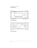
Страница 242: ...7 12 Specifications and Regulatory Information Regulatory Information Front view of instrument Rear view of instrument ...

Страница 243: ...8 Instrument Preset Conditions 8 2 Menu Maps 8 4 Error Messages 8 9 Front Panel Fiber Optic Adapters 8 15 Power Cords 8 16 Agilent Technologies Service Offices 8 18 Reference ...

Страница 244: ... last statea Wavelength range limiting on last state Start wavelength 1200 nm last state Stop wavelength 1650 nm last state Graphical display off off Measurement acquisition continuous last state Wavelength calibration vacuum last state Elevation correction value not affected last state Wavelength units nm last state Amplitude units dBm last state Power offset 0 dB last state Peak threshold 10 dB ...

Страница 245: ...erence signal position 700 nm 700 nm Signal to Noise Measurements measurement off off wavelength reference auto last state user wavelength not affected last state number of averages 100 last state GPIB address not affected last state Power bar display on last state a The term last state refers to the last setting that this parameter was in before the instrument power was turned off Table 8 1 Instr...

Страница 246: ... maps show which softkeys are displayed after pressing a front panel key they show the relationship between softkeys The softkeys in these maps are aligned ver tically instead of horizontally as on the actual display This was done to con serve space and to make the maps easier to interpret Appl s Menu ...

Страница 247: ...8 5 Reference Menu Maps Display Avg WL Menu There is no menu associated with this key Measurement Cont Menu There is no menu associated with this key Display List by Power Menu Display List by WL Menu ...

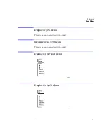
Страница 248: ...8 6 Reference Menu Maps Delta On Menu Delta Off Menu ...

Страница 249: ...8 7 Reference Menu Maps Display Peak WL and System Preset Menus Measurement Single Menu There is no menu associated with this key System Print Menu ...

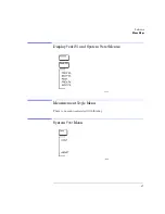
Страница 250: ...8 8 Reference Menu Maps System Setup Menu ...

Страница 251: ...pecific Error Messages 1 of 3 Error Number Error Message 1 BAD CHECKSUM FROM MOTOR 2 MOTOR COMMUNICATION PROBLEM 3 MOTOR NOT MOVING 4 MOTOR INDEX PULSE NOT FOUND 5 MOTOR CHIP SET INIT FAILED 6 MOTOR COMMUTATION FAILURE 7 MOTOR NOT SETTLED 8 MOTOR DID NOT STOP 9 MOTOR MOTION ERROR 10 MOTOR POSITION LIMIT FAILED 11 MOTOR POSITION WRAP FAILED 12 POWER LEVEL TOO HIGH 13 DATA DOWNLOAD PROBLEM 14 DATA A...

Страница 252: ... BAD CAL ROM DATA 27 BAD CAL ROM DATA 28 BAD CAL ROM DATA 29 BAD CAL ROM DATA 30 NVSRAM WRITE OPERATION FAILED 31 SOFTWARE INITIALIZATION FAIL 32 HARDWARE INITIALIZATION FAIL 33 INITIALIZATION TIMEOUT 34 BATTERY FAILED 36 TOO MANY ERRORS 37 FUNCTION NOT YET IMPLEMENTED 38 PRINTER OFF LINE 39 PRINTER OUT OF PAPER 40 PRINTER ERROR DETECTED 41 PRINTER TIMED OUT Table 8 2 Instrument Specific Error Mes...

Страница 253: ...WED IN COH LEN 44 NOT ALLOWED IN S N 45 UNKNOWN KEYPRESS 46 NUM LINES NUM REFS 47 NUM LINES NUM REFS 48 NO REFERENCE SIGNAL 49 GAIN RANGING ERROR 50 INCOMPATIBLE HARDWARE 51 UNKNOWN ERROR Table 8 2 Instrument Specific Error Messages 3 of 3 Error Number Error Message ...

Страница 254: ...pe error 105 GET not allowed 108 Parameter not allowed 109 Missing parameter 112 Program mnemonic too long 113 Undefined header 120 Numeric data error 121 Invalid character in number 123 Exponent too large 124 Too many digits 128 Numeric data not allowed 131 Invalid suffix 134 Suffix too long 138 Suffix not allowed 141 Invalid character data 148 Character data not allowed 150 String data error 151...

Страница 255: ...ous measurement mode 221 Settings conflict Caused by trying to set the instrument to a state that is not allowed For example turning on drift maximum and drift minimum state simultaneously or turning on SNR state while drift or delta state is on 222 Data out of range 223 Too much data 224 Illegal parameter value 230 Data corrupt or stale Caused by trying to query measurement data immediately after...

Страница 256: ... many errors 400 Query error 410 Query INTERRUPTED 420 Query UNTERMINATED 430 Query DEADLOCKED 440 Query UNTERMINATED after indef resp Query was unterminated after an indefinite response Table 8 3 General SCPI Error Messages 3 of 3 Error Number Description ...

Страница 257: ...ent Part Number Diamond HMS 10 81000AI FC PCa a The FC PC is the default front panel optical connector 81000FI D4 81000GI SC 81000KI DIN 81000SI ST 81000VI Biconic 81000WI Dust Covers Agilent Part Number FC connector 1005 0594 Diamond HMS 10 connector 1005 0593 DIN connector 1005 0595 ST connector 1005 0596 SC connector 1005 0597 ...

Страница 258: ... Gray Coco Brown East and West Europe Saudi Arabia So Africa India unpolarized in many nations 125V 8120 1378 8120 1521 8120 1992 Straight NEMA5 15P 90 Straight Medical UL544 90 228 90 228 96 244 Jade Gray Jade Gray Black United States Canada Mexico Philippines Taiwan 250V 8120 2104 8120 2296 Straight SEV1011 1959 24507 Type 12 90 79 200 79 200 Mint Gray Mint Gray Switzerland 220V 8120 2956 8120 2...

Страница 259: ...India 100V 8120 4753 8120 4754 Straight MITI 90 90 230 90 230 Dark Gray Japan Plug Type Cable Part No Plug Description Length in cm Color Country Part number shown for plug is the industry identifier for the plug only Number shown for cable is the Agilent Technologies part number for the complete cable including the plug ...

Страница 260: ...numbers listed below Agilent Technologies Service Numbers Austria 01 25125 7171 Belgium 32 2 778 37 71 Brazil 11 7297 8600 China 86 10 6261 3819 Denmark 45 99 12 88 Finland 358 10 855 2360 France 01 69 82 66 66 Germany 0180 524 6330 India 080 34 35788 Italy 39 02 9212 2701 Ireland 01 615 8222 Japan 81 426 56 7832 Korea 82 2 3770 0419 Mexico 5 258 4826 Netherlands 020 547 6463 Norway 22 73 57 59 Ru...

Страница 261: ...sterisk 2 4 2 6 2 15 attenuation See external attenuation audio modulation effects of 2 16 2 23 AUTO programming command 5 60 softkey 3 6 AVERAGE annotation 2 7 average wavelength iii 2 7 Avg WL key 2 7 2 8 B BAR OFF softkey 2 12 BAR ON softkey 2 12 beta factor 3 12 3 14 BETA programming command 5 25 bit error rate 3 3 block diagram 4 5 BROAD annotation 2 10 BROAD softkey 2 10 broadband devices me...

Страница 262: ... 13 Cont key 2 15 3 10 CONT softkey 2 29 CONTinuous programming command 5 85 cotton swabs 1 20 covers dust 8 15 cursor 2 6 D damaged shipment 1 3 data corrupt or stale 4 26 5 8 8 13 data questionable 8 13 DATA programming command 5 27 5 32 5 46 5 73 DBM softkey 2 14 default GPIB address 4 3 DELay programming command 5 25 Delta Off softkey See Off Delta On softkey See On DEVICES softkey 2 10 DFB la...

Страница 263: ...ring 1 24 firmware version iii 2 10 5 70 displayed 1 9 over GPIB 5 6 flatness 7 4 7 7 FNIdentity function 4 29 foam swabs 1 20 FREQuency programming command 5 19 5 48 5 61 front panel adapters 8 15 labels 7 12 lockout 4 3 fuse 1 5 drawer 1 5 extra 1 5 type 1 5 values vii G GPIB address 4 3 address changing from front panel 4 3 address default 4 3 softkey 4 3 H hardcopy See printer HCOPy subsystem ...

Страница 264: ...dulation 2 16 2 23 audio modulation effects of 2 16 2 23 average wavelength 2 7 calibration 2 26 channel separation 2 22 channel spacing 2 21 coherence length 3 12 continuous acquisition 2 15 cycle time 7 5 7 8 definition of peaks 2 16 elevation effects of 2 26 flatness 2 22 via GPIB 4 5 instructions 4 23 5 15 laser drift 3 9 laser line separation 2 20 low power laser lines effects of 2 18 modulat...

Страница 265: ...6 power iii 2 4 threshold limit 2 16 2 19 2 24 wavelength iii 2 4 Peak WL key 2 4 menu map 8 7 softkey 2 4 3 10 performance tests 6 2 PEXCursion programming command 5 33 PK EXC softkey 2 19 PK THLD softkey 2 19 POINts programming command 5 29 5 34 5 59 polarization dependence 7 4 7 7 power bar iv 2 4 2 12 maximum input iv maximum measurable 2 2 measuring total 2 7 5 32 5 35 peak 2 4 separation 2 2...

Страница 266: ...ic distortion 2 18 SELECT softkey 2 6 2 21 selectivity 7 4 7 8 semicolon 4 23 sending common commands 4 25 SENSe subsystem 5 69 sensitivity 7 4 7 7 serial number instrument 1 3 service 1 23 request enable register 4 20 5 10 returning for 1 23 sales and service offices 8 18 Set_ese subroutine 4 28 settings conflict error 4 14 5 36 5 45 5 47 5 51 5 52 5 54 5 55 5 57 5 58 5 64 8 13 Setup key 1 12 2 8...

Страница 267: ... 14 uppercase letters 4 24 USER softkey 3 6 USER WL softkey 3 6 UW softkey 2 14 V VAC annotation 2 26 VACuum programming command 5 72 VACUUM softkey 1 11 2 27 vacuum measurements in 2 26 VERSion programming command 5 83 W WAI 5 14 wave number 2 14 wavelength definition of 7 3 input range 2 2 peak 2 4 range 2 8 4 4 5 36 separation 2 20 specifications 7 6 WAVelength programming command 5 21 5 49 5 6...

Страница 268: ......

Отзывы: