Installation, assembly and setting
Assembly instructions EN
DG 16
Edition 07/2020
Rev. 3.0
33–50
6.3.3 Connection to the pneumatic system
There are pneumatic connections on 4 sides of the rotary gripper body. The
connections at the rear of the rotary gripper are open by default.
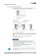
1. Rotary gripper
3. Maintenance unit
2. Way valve (stand. 4/2) P: Air connection
Fig. 14
Pneumatic diagram DG 16
To ensure a reliable “gripping” monitoring we recommend setting the signal “Part
gripped” at half the jaw stroke length. The full jaw stroke length should not be
limited.
Example: DG 16 Jaw stroke 2x3 mm
Part gripped at 2x1.5 mm
Operating pressure: 6 bar +/-1 bar
The minimum compressed air quality shall comply with the specifications of
ISO 8573-1:2010.
NOTICE
Functional impairment to leaking compressed air connections!
Unused air connections that are not hermetically sealed lead to a pressure
loss and thus to functional impairment.
Before installing the rotary gripper module in a system, all unused
compressed air connections must hermetically sealed.
Perform a leakage test!


