TF7039GB_A_NOT
Page 30 of 48
switchable from
S1.8 “F” to 1 minute) (+/- 10%), an error is displayed (red LED and contact X4 “NC-NO-
COM”).
For the operator, visual displays are available for information and to control the functions. The presence of
mains voltage is indicated by a green LED. Setback mode is indicated by a yellow LED. The three-digit
display shows the measured pressure in control mode, otherwise an error code “Exx” or calibration mode
“CAL”. Error messages are additionally indicated by a red LED.
6.2.3.
PRESSURE LEVEL SETPOINT VALUE SPECIFICATION
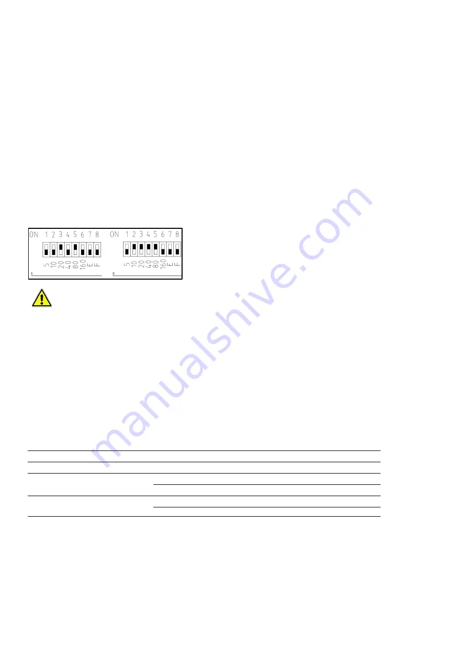
The setpoint for the differential pressure in normal operation is set at pins 1-6 of switch S1 (
A
). The sum of
all pins gives the setpoint in Pascal.
Value range: 5...300 Pa
Increments: 005-155 Pa in steps of 5 Pa
160-300 Pa in steps of 10 Pa
Examples:
Setpoint A = 100 Pa
Setpoint B = 150 Pa
Caution! Not all pins 1-
6 may be set to “ON” at the same time. This puts the controller into “cali-
bration mode”. The maximum permissible setpoint is 300 Pa. The setpoint is set to 100 Pa ex
works. If the measured air volume flows are too large or too small during commissioning, the
pressure level can be lowered or raised in 20 Pa steps, for example, and later in smaller steps for
fine adjustment.
6.2.4.
PRESSURE CONTROL DISPLAY ELEMENTS
D
“Network” LED
E
Pressure indicator
M
“Setback mode” LED
N
“Error” LED
Element
Display
Meaning
“Network” LED (green)
Solid light
Mains voltage on
“Setback mode” LED (yellow)
Solid light
Setback mode is active
“Error” LED (red)
Flashing slowly
Pressure setpoint undershot
Flashing quickly
Pressure setpoint overshot
Display
approx. “000”
Sensor without differential pressure
e.g. “120”
Current differential pressure (example)


