


12-17-2018
Information subject to change
35
3110 HELP FILES – SECTION 6
NOTE: GPIO ports and controls
are not supported on DSR Series
systems.
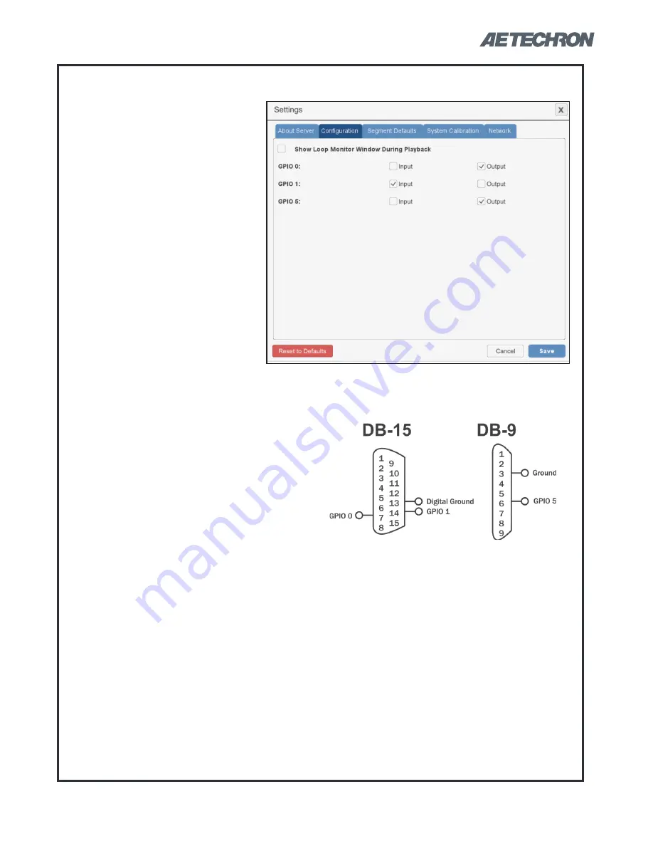
The GPIO Setup checkboxes are
used to configure the usage of the
3110’s three dedicated GPIO ports.
These ports can be accessed us-
ing the 3110’s DB-15 connector
using pins 7 and 14 (referenced to
ground on pin 13), and the DB-9
connector using pin 6 (referenced
to ground on pin 3). See
Figure
6.7
.
IMPORTANT:
The GPIO pins are
tied directly to the microprocessor
and are not isolated. Take care not
to exceed maximum ratings as per-
GPIO Setup
manent damage can occur. We highly recom-
mend optical isolation (opto-coupler, solid state
relay, etc.) be used on all GPIO pins before
connecting to external equipment.
Each GPIO port can be configured as an Input
or an Output.
GPIO Input:
When a GPIO port is configured
as an input, it can be used in a GPIO Trig-
ger segment. When a GPIO Trigger segment
is reached in a test sequence, the 3110 will
pause and wait for the specified signal to be
received on the designated GPIO port. When
the signal is received, the test sequence will
continue with the next segment following the
trigger. NOTE: Only one GPIO port should be
configured as an Input for use as a Trigger.
The electrical characteristics of a GPIO port
when programmed as an input:
Voltage: Logic 0 = 0VDC; Logic 1 = 3.3VDC
Impedance: =>10 Mohm
GPIO Output:
When a GPIO port is configured
as an output, it can be used in a GPIO Output
segment. See the Help topic
“GPIO Output
Control”
for information on GPIO Output prop-
erties.
After assigning the pins as required for your
use or application, press the Save button
to save the settings. and then use the cor-
responding pins to program a GPIO Trigger
segment.
Figure 6.7 – GPIO Pinouts on DB15
and DB-9 Connectors


