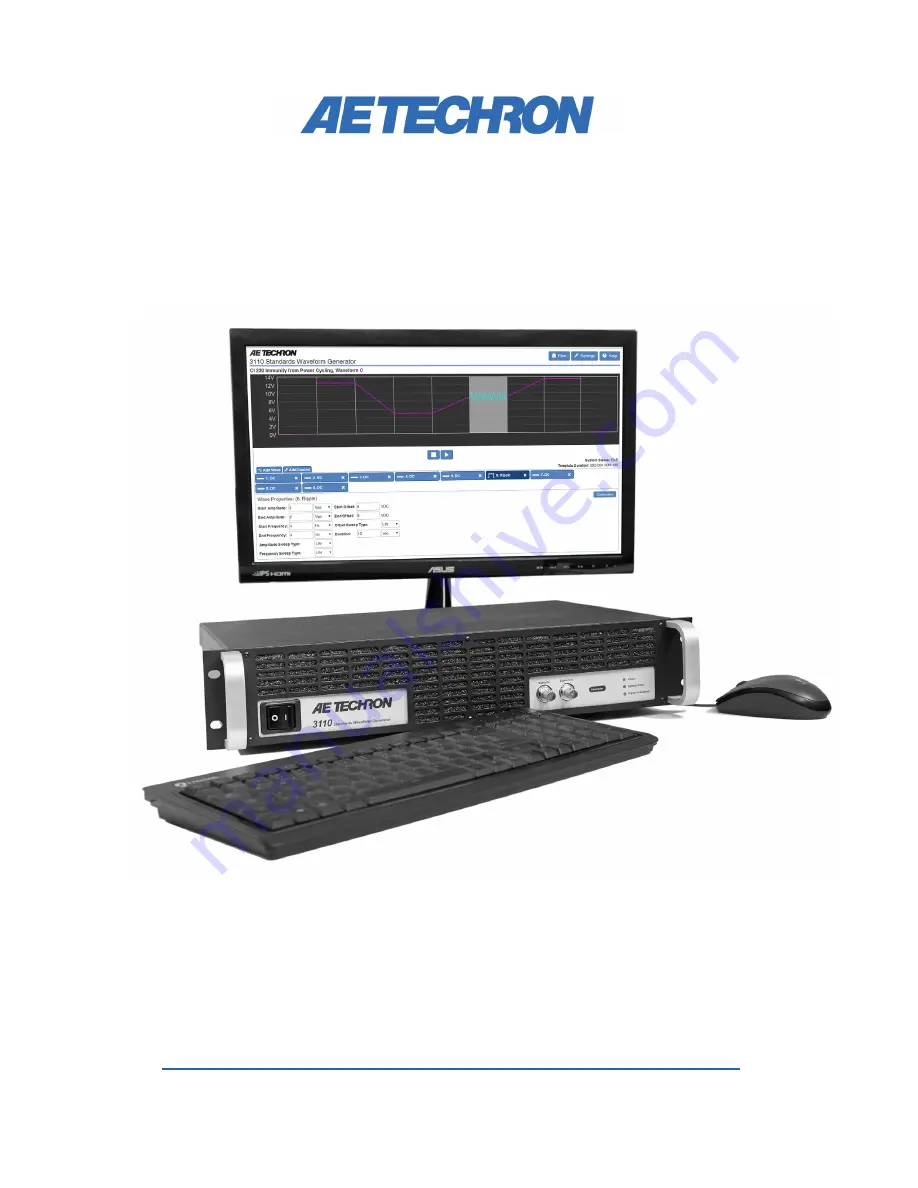
3110
Standards Waveform Generator
Help Files and Product Reference
574.295.9495 |
www.aetechron.com
2507 Warren Street, Elkhart, IN 46516
Страница 1: ...3110 Standards Waveform Generator Help Files and Product Reference 574 295 9495 www aetechron com 2507 Warren Street Elkhart IN 46516 ...
Страница 2: ...CHRON INC of Elkhart Indiana Warrantor war rants to you the ORIGINAL COMMERCIAL PURCHASER ONLY of each NEW AE TECHRON INC product for a period of one 1 year from the date of purchase by the original purchaser warranty period that the product is free of defects in materials or workmanship and will meet or exceed all advertised specifications for such a product This warranty does not extend to any s...
Страница 3: ... 14 4 3 Working in Demo Mode 16 4 4 USB Drive 16 4 5 Updating the 3110 DSR System 17 4 6 Using the 6 to 1 Attenuator 18 4 7 Shutdown Procedure 19 5 Tutorials 20 5 1 3110 Basic Operation Tutorial 20 5 2 Working with Waves and Controls Tutorial 22 5 3 Running a Test 24 5 4 Creating an Exponential Sweep 24 6 Waveforms and Controls 27 6 1 Alternating Waves 27 6 2 Ripple Wave 30 6 3 DC Signal 32 6 4 Co...
Страница 4: ...from convex to concave Simultaneous Sine Generation for Modulation Can superimpose a higher frequency on a lower frequency sine wave or fundamental Calibration on Segments within Scripted Variable Loops Can command voltage changes to adjust output to test required voltages in discrete frequency step standards Remaining Time The user can see total time for the test and elapsed time for the test Sea...
Страница 5: ...accompanying amplifier modules or it can be used independently with many other audio bandwidth amplifiers The 3110 also can be purchased as a stand alone unit and can be readily combined with new or existing AE Techron 7000 series amplifiers to create custom modular test systems AE Techron s 7200 series and 7700 series amplifiers can be easily configured into series or parallel multi amp systems f...
Страница 6: ...the 3110 back panel C Plug the HDMI to DVI cable into the HDMI port labeled MONITOR on the 3110 back panel and then connect the cable to the DVI port on the monitor D Plug the monitor power cord into the monitor and then connect the cord to a power source E Plug the 3110 power cord into the power con nector located on the 3110 back panel and then connect the cord to a power source F OPTIONAL To co...
Страница 7: ...ps to power up a 3110 unit and a connected power amplifier Figure 2 2 Connecting an amplifier to the3110 B Depress the 3110 POWER switch to turn the 3110 ON Figure 2 3 Monitor on off switch Figure 2 4 3110 on off switch Figure 2 5 Amplifier gain control and power switch Figure 2 6 Electronic Help manual C If the amplifier has a gain control turn it fully ON clockwise Then turn the POWER switch ON ...
Страница 8: ...d at the system s output These levels are calculated based on the Measured Output and Measured DC Offset settings entered on the System Calibration tab in the Settings window In DSR Series systems the system calibration settings will be factory set based on the number of amplifiers in the system For stand alone 3110 s the factory default is set to a System Gain of 20 and a DC Offset of 0 which are...
Страница 9: ...the Settings but ton and then open the System Calibration tab 2 Adjust the 3110 Output Volt age if desired A default test signal of 1 Vp will be pre entered in this box Note the default DC offset is 0 and cannot be changed 3 Connect an oscilloscope to the DUT load at the system output 4 Press the Run Calibration Test button to begin the Cali bration Test The 3110 will generate a 1 kHz sine wave si...
Страница 10: ...tics at the beginning state of the sweep will be gener ated If the tested output voltage does not match the specified voltage calculate the amount re quired to adjust the output voltage by dividing the specified output voltage by the measured output voltage Enter the results into the Wave Gain input box For example if the tested output is measured at 10 1V but the specified voltage is 10V divide 1...
Страница 11: ...n select a waveform segment contained within a scripted variable loop Then press the Calibration button to open the Cali bration Values window See Figure 3 7 The values for all scripted variables in the first iteration of the segment within the variable loop will be shown in the Calibration Values window Determine the variable that defines the amplitude of the segment all scripted variable loops i...
Страница 12: ...ress the Stop Calibration Test button The calibra tion test will stop and you will be returned to the initial Calibration Test window Note that the new amplitude values that have been calculated by the SWG software will be shown in the Value column Press the Close button to close the Calibration window Or if you prefer press the blue Next button to go to the next segment in your test se quence to ...
Страница 13: ...click on the Demo Mode message to open the network Figure 4 1 Main window controls and functions connection window See the topics Working in Demo Mode and Remote Operation later in this section for more information B Test Sequence Display Wave and control segments added to the test sequence are visu ally displayed in this area Wave segments will be represented with a waveform approximat ing the si...
Страница 14: ...Running a Test for more information L System Status message The System Status message will display the state of the 3110 as Idle whenever a test sequence is not running The status will also be shown as Idle at all times when operating in Demo Mode When the Run button is pressed the System Status message will display a running count of the time elapsed in the test Alternately if the Total Duration ...
Страница 15: ...ork administrator for assistance 3 Insert the USB drive included with the 3110 DSR system into an open USB port on the Figure 4 3 3110 IP Address Listing Figure 4 4 Remote Connection to the 3110 DSR System computer to be used for accessing the 3110 DSR system across the network Open the USB drive and then locate and install and the Windows Remote Client installation file named Setup exe 4 When the...
Страница 16: ... Figure 3 4 A local copy of the 3110 Standards Library is cop ied to the Windows computer when the Remote Client software is installed so you can load tests from the Standards Library to use as a template to edit and save as a new test file You can use the Add Wave and Add Control buttons to create new waveform sequences When the test sequence is complete press the Files button to save the swg fil...
Страница 17: ...m See the following topic Up dating the 3110 for more information 4 5 Updating the 3110 DSR System Updates for the 3110 software including addi tions to the Standards Library and the Windows Remote Client software are available on the AE Techron website aetechron com NOTE When updating the 3110 software all Windows comput ers used to access the 3110 remotely must also be updated with the correspon...
Страница 18: ...dialog and the 3110 Remote Client will automatically load 4 Check the version information displayed on the About Server tab in the Settings window to confirm the update has been successfully installed 4 6 Using the 6 to 1 Attenuator NOTE A 6 1 attenuator is built into DSR Series systems See the DSR Series Operation Manual for information on using the DSR system s built in attenuator A BNC male to ...
Страница 19: ...4 7 Shutdown Procedure IMPORTANT Any powered amplifiers that are connected to the 3110 must first be disabled before shutting down the 3110 or DSR System Failure to follow the proper shutdown procedure can result in damage to the amplifiers or any con nected load DUT Complete the following to safely shut down a 3110 amplifier combination or DSR System 1 Make sure all amplifiers connected to the sy...
Страница 20: ... learn about these opera tions 5 1 3110 Basic Operation Tutorial 1 Select the Settings button and then open the System Calibration tab to set the 3110 system gain and DC offset The default gain setting is 20 but this should be calibrated to match your actual system gain When measuring 3110 output directly without amplification the system gain can be set to 1 for a maximum of 10Vp 20Vpp output See ...
Страница 21: ... Select the tab for a waveform or control to open the Properties dia log Edit the properties to create complex waveforms and wave form sequences 5 Segments can be dragged to change their order To remove a segment from the test press the X on the segment s tab 6 When your test sequence is complete press the Arrow button to begin generating signal output from the amplifier ...
Страница 22: ...emplate GPIO Output or LAN Output Choose the Sine waveform from the Add Wave drop down menu A sinewave with the program s default settings will be added to the display 2 Click on the tab or the wave form in the display to open the Properties window containing the available property settings for that waveform See the section Waveforms and Controls in this Help manual for more infor mation about the...
Страница 23: ...values for that property Enter a value outside of that range for example 500 Vp The entry field will change to red and the allowable range will be dis played within the field Enter the value 1 Vp or another allowable value to remove the error 5 Add additional waveforms to the test by selecting additional waveforms from the drop down menu New wave forms will be inserted to the right of the selected...
Страница 24: ...ster as being highlighted 6 Press the Pause button The system will stop generating the signal described in the test se quences By default the controller will gener ate no signal while a test is paused To gener ate a predetermined DC signal instead change the Pause Voltage setting on the Configuration tab in the Settings window See Figure 5 15 7 Press the Run button The system will begin generating...
Страница 25: ...eep 8 EXP Duration 1000 ms 5 Set the third segment s properties as follows Start Offset 10 End Offset 0 Offset Sweep 8 EXP Duration 1000 ms 6 Set the third segment s properties as follows Start Offset 10 End Offset 0 Offset Sweep 8 EXP Duration 1000 ms 7 Run the test sequence The resulting output should be similar to that shown in Figure 5 17 Note that a rising exponential will be concave when a p...
Страница 26: ... SECTION 5 26 Note that higher values for the effective time constant property will result in a steeper slope on the exponential Figure 5 17 Comparison of Effective Time Sign Constant Settings Figure 5 18 Comparison of Effective Time Constant Value Settings ...
Страница 27: ...gle waveform DC to 20 kHz Square Wave The 3110 uses its arbitrary wave form generator to create the specified square wave output Select Square from the Add Wave drop down when you need to create an audio frequency square waveform DC to 20 kHz Sawtooth Wave The 3110 uses its arbitrary waveform generator to create the specified saw tooth wave output Select Sawtooth from the Add Wave drop down when y...
Страница 28: ...e range from 8 to 8 Increase or decrease this variable to affect the rate of exponential change To change the expo nential curve from convex to concave vary the sign of the effective time constant See the topic Creating an Exponential Sweep in the Tutori als section for more information Clip Amplitude Select the Clip Amplitude check box to enable the waveform clip feature When enabled the Clip Amp...
Страница 29: ...ely regardless of the duration time set in that wave form s properties If no additional waveform has been defined to fol low the completed waveform the system output will stop Ripple Select the Ripple checkbox to enable the Ripple feature When enabled Ripple will produce a modulation effect on an AC wave by superim posing a higher frequency on a lower frequency fundamental waveform Enter the desir...
Страница 30: ...range is 200Vp with system gain set to 20 This range is displayed above the selected input box When a value outside of the allowable range is entered the input box will turn red Frequency The Start Frequency and End Fre quency properties determine the frequency of the wave in cycles per second Hertz Frequency can be defined using Hertz Hz or Kilohertz kHz as the unit of measure When the unit of me...
Страница 31: ...perties window The effective time constant has an allowable range from 8 to 8 Increase or decrease this variable to affect the rate of exponential change To change the expo nential curve from convex to concave vary the sign of the effective time constant See the topic Creating an Exponential Sweep in the Tutori als section for more information Duration The Duration property determines how long the...
Страница 32: ...p type from the drop down Figure 6 3 DC Signal Properties When Exponential is chosen as the sweep type an additional variable the effective time constant is added to the properties window The effective time constant has an allowable range from 8 to 8 Increase or decrease this variable to affect the rate of exponential change To change the expo nential curve from convex to concave vary the sign of ...
Страница 33: ...ntrols including GPIO Trigger and GPIO Output are not supported on DSR Series systems 6 4 1 Trigger Control The Trigger Control will cause a a running test to pause and wait for an input that will cause the trig ger to release Figure 6 4 User Trigger Properties To create a trigger within a test select the Trigger option from the Add Control drop down menu A Trigger icon will be added to the active...
Страница 34: ...ou have previ ously designated as the GPIO input during GPIO setup After you have selected a GPIO monitor as true you will be prompted to choose the logic state 0 or 1 that will cause the trigger to be released Cont Prev Waveform When the trigger is released the 3110 will begin generating the next waveform in the test sequence While waiting for the trigger the 3110 will continue to generate the wa...
Страница 35: ... or an Output GPIO Input When a GPIO port is configured as an input it can be used in a GPIO Trig ger segment When a GPIO Trigger segment is reached in a test sequence the 3110 will pause and wait for the specified signal to be received on the designated GPIO port When the signal is received the test sequence will continue with the next segment following the trigger NOTE Only one GPIO port should ...
Страница 36: ...Loop Count property found under the Fixed Loop Start tab See Figure 6 8 To create a fixed loop within a test select the Fixed Loop option from the Add Control drop down menu in the 3110 s main window Two control icons Fixed Loop Start and Fixed Loop End will be added to the active test sequence Drag the waveform s to be repeated so they are positioned between the Fixed Loop icons Select the Fixed ...
Страница 37: ...inear Then find the property controls for the variable letter you just assigned In the Variable Start input box enter the setting you want for that property at the beginning of the loop sequence first loop In the End input box enter the setting you want for that property at the end of the loop sequence last loop Last input the amount the variable should increase or decrease from one loop to the ne...
Страница 38: ...an be as signed between the two variable loops Variables assigned in the outer loop are also available to the inner loop and can be reused However if the same variable letter is defined in both an outer and an inner Variable Loop the variable assignment from the outer Variable Loop takes precedence and will be applied to all variables with the same letter assignment Scripted Variable Loops Scripte...
Страница 39: ...l appear below the Control Properties in the Properties window See Figure 6 14 5 Select the waveform tab to open the waveform properties Assign each variable from the csv file to the waveform proper ties as required See Figure 6 15 6 When all variable have been assigned press the Arrow play button to begin generating the signal Note that the test data and test notes imported into the SWG file will...
Страница 40: ...est sequence is stopped the loop monitor count will also be stopped If the test is restarted the loop monitor count will be reset to the begin ning of the count Use the X in the upper right of the Loop Monitor window to close the window Note that this will also prevent the Loop Monitor window from opening for this or other tests until the Loop Monitor check box is selected again on the Configurati...
Страница 41: ...a test sequence IMPORTANT Before configuring the GPIO Output Control each GPIO port must first be configured to function as an input or an output using the GPIO Setup controls on the Configuration tab located under Settings Please refer to the GPIO Setup instructions provided in the sidebar on the next page If a GPIO port has been configured as an input in the GPIO Setup controls that port can be ...
Страница 42: ...red as an Input or an Output GPIO Input When a GPIO port is configured as an input it can be used in a GPIO Trig ger segment When a GPIO Trigger segment is reached in a test sequence the 3110 will pause and wait for the specified signal to be received on the designated GPIO port When the signal is received the test sequence will continue with the next segment following the trigger NOTE Only one GP...
Страница 43: ... on Open When a test is saved in the User Standards directory as a custom test file Figure 7 1 Using the Report Notes Feature 7 Creating Reports and Notes Select the Report Notes button from the main menu to access the 3110 Report Generator The Report Generator provides several pre defined input areas to identify important test information including company report tester customer standard applicat...
Страница 44: ...stom test To automatically open the Report Generator window when the test file opened select the option Show Notes on Open Detailed Report When Detailed Report is select ed a detailed listing of all test waveform param eters and sequences will be included in the gener ated rtf file See the detailed report in Figure 7 2 Figure 7 2 Detailed Report Sample ...
Страница 45: ...ing All files contained in the Standards library are Read Only User Standards The User Standards directory is a write able storage space to be used to store user created custom tests and test variations Files saved in the User Standards directory can be copied altered and deleted Subdirectories can be added to the User Standards directory To open a pre programmed swg file open the Files window and...
Страница 46: ...ened the files and or folders one level lower in the file system hierarchy will be shown in the Files window When a file is selected pressing the Open button will cause the file to be loaded into the 3110 s main window Double clicking on a folder or file in the Files window will also function the same as press ing the Open button Delete Press the Delete button to delete the se lected folder s or f...
Страница 47: ...y memory into the cur rent location in the User Standards directory Note that swg files cannot be pasted into the Standards library Unmount USB Press the Unmount USB button to unmount the USB drive before removing the drive from the USB port If the Unmount USB button is not pressed before removing the USB drive the 3110 may not recognize the USB drive when it is returned to the USB port If the USB...
Страница 48: ...ed and is used for diagnostic purposes See Figure 9 1 9 4 2 The Configuration Tab The Configuration tab allows the control for the loop monitor window to be toggled on and off and also provides the controls for GPIO setup See Figure 9 2 Loop Monitoring The Loop Monitoring checkbox turns the loop monitor window on or off When the box is checked the loop monitor window will be dis played during test...
Страница 49: ... can be used in a GPIO Trig ger segment When a GPIO Trigger segment is reached in a test sequence the 3110 will pause and wait for the specified signal to be received on the designated GPIO port When the signal is received the test sequence will continue with the next segment following the trigger NOTE Only one GPIO port should be configured as an Input for use as a Trigger The electrical characte...
Страница 50: ...tory defaults select the Reset to Defaults button See Figure 9 4 9 4 4 The System Calibration Tab The System Calibration tab holds information about the output generated by the DSR system or the combined 3110 amplifier system See Figure 9 5 Both system gain and system DC offset informa tion are used by the 3110 to adjust its signal output to produce the expected signal at the amplifier out put By ...
Страница 51: ...ystem requires a reboot of the 3110 Before rebooting the 3110 make sure all amplifiers connected to the system are disabled To quickly disable AE Techron amplifiers press the Stop button on the front panel of any amplifier to place all connected units in Standby mode Con sult the instructions for non AE Techron amplifiers to determine the best method for disabling those units After all amplifiers ...
Страница 52: ...abling those units After all amplifiers have been disabled the 3110 can be safely rebooted by pushing the 3110 s front panel power switch to the OFF position and then switching back to the ON position To return all AE Techron amplifiers to Run status press the Enable button on the same amplifier that was used to place the amplifiers in Standby mode 5 Be sure to save any unsaved unsaved swg test fi...
Страница 53: ...ed To quickly disable AE Techron amplifiers press the Stop button on the front panel of any amplifier to place all connected units in Standby mode Con sult the instructions for non AE Techron amplifiers to determine the best method for disabling those units After all amplifiers have been disabled the 3110 can be safely rebooted by pushing the 3110 s front panel power switch to the OFF position and...
Страница 54: ...ocated in a compart ment above the back panel AC power connector protects the unit Remove the compartment cover to access the fuse and replace the fuse if needed PROBLEM Experiencing noise during testing A Install the 6 1 attenuator provided with the 3110 Adjust the system gain as instructed to improve the system s signal to noise performance See the topic Using the 6 to 1 Attenuator in the Op era...
Страница 55: ...urately measure the quanti ties in Table 1 within the tolerances provided In struments should bear evidence via a label on the instrument or similar documentation that the mea suring instrument is calibrated The table shown below is provided to record the performance of the 3110 in key areas and to facilitate interaction with the AE Techron when needed ANSI Z540 or ISO 17205 calibration with docu ...
Страница 56: ...n the triggering selected The test varies voltage and for alternat ing waveforms a range of frequencies is given for each voltage level Set up the test waveforms in the User Defined Standards Directory 11 4 5 Procedure for Phase Testing A Create a 0 VDC segment of short duration no more than a few seconds B Insert a trigger True after the 0 VDC segment C Insert a ripple waveform with the following...
Страница 57: ...00 NA NA 4 9 5 1 200 NA NA 9 9 10 1 Ripple Start End Amplitude Vp Frequency kHz Measured Frequency kHz Low Limit Vp Measured V High Limit Vp 100 1 4 8 5 3 10 4 8 5 3 100 4 8 5 3 300 3 5 3 6 200 1 9 5 10 5 10 9 5 10 5 20 9 5 10 5 Sawtooth Start End Amplitude Vp Frequency kHz Measured Frequency kHz Low Limit V Measured V High Limit V 100 1 4 8 5 3 10 4 8 5 3 20 4 8 5 3 200 1 9 5 10 5 10 9 5 10 5 20 ...
Страница 58: ...OSE ARE DISCLAIMED IN NO EVENT SHALL THE COPYRIGHT OWNER OR CONTRIBUTORS BE LIABLE FOR ANY DIRECT INDIRECT INCIDENTAL SPECIAL EXEMPLARY OR CONSEQUENTIAL DAM AGES INCLUDING BUT NOT LIMITED TO PROCURE MENT OF SUBSTITUTE GOODS OR SERVICES LOSS OF USE DATA OR PROFITS OR BUSINESS INTER RUPTION HOWEVER CAUSED AND ON ANY THEORY OF LIABILITY WHETHER IN CONTRACT STRICT LIABILITY OR TORT INCLUDING NEGLIGENC...
Страница 59: ... notices are retained in all copies and that this notice is included verbatim in any distributions No written agreement license or royalty fee is required for any of the authorized uses Modifications to this software may be copyrighted by their authors and need not follow the licensing terms described here provided that the new terms are clearly indicated on the first page of each file where they ...
Страница 60: ...IMED IN NO EVENT SHALL THE AUTHOR OR CONTRIBUTORS BE LIABLE FOR ANY DIRECT INDIRECT INCIDENTAL SPECIAL EXEMPLARY OR CONSEQUENTIAL DAMAGES INCLUDING BUT NOT LIMITED TO PROCUREMENT OF SUBSTITUTE GOODS OR SERVICES LOSS OF USE DATA OR PROFITS OR BUSINESS INTERRUPTION HOWEVER CAUSED AND ON ANY THEORY OF LIABILITY WHETHER IN CONTRACT STRICT LIABILITY OR TORT INCLUD ING NEGLIGENCE OR OTHERWISE ARISING IN...
Страница 61: ... com All rights reserved Redistribution and use in source and binary forms with or without modification are permitted provided that the following conditions are met 1 Redistributions of source code must retain the above copyright notice this list of conditions and the following disclaimer 2 Redistributions in binary form must reproduce the above copyright notice this list of conditions and the fol...
Страница 62: ...used in advertising or publicity per taining to distribution of the software without specific written prior permission Hewlett Packard Company makes no representations about the suitability of this software for any purpose 21 Henry Spencer only linux targets Copyright 1992 1993 1994 Henry Spencer All rights reserved This software is not subject to any license of the American Telephone and Telegrap...
Страница 63: ...OF THE POS SIBILITY OF SUCH DAMAGE 25 IBM Sony Toshiba only spu targets C Copy right 2001 2006 International Business Machines Cor poration Sony Computer Entertainment Incorporated Toshiba Corporation All rights reserved Redistribution and use in source and binary forms with or without modification are permitted provided that the following conditions are met Redistributions of source code must ret...
Страница 64: ...TS OR CONTRIBUTORS BE LIABLE FOR ANY DIRECT INDIRECT INCIDENTAL SPECIAL EXEMPLARY OR CONSEQUENTIAL DAM AGES INCLUDING BUT NOT LIMITED TO PROCURE MENT OF SUBSTITUTE GOODS OR SERVICES LOSS OF USE DATA OR PROFITS OR BUSINESS INTER RUPTION HOWEVER CAUSED AND ON ANY THEORY OF LIABILITY WHETHER IN CONTRACT STRICT LIABILITY OR TORT INCLUDING NEGLIGENCE OR OTHERWISE ARISING IN ANY WAY OUT OF THE USE OF TH...
Страница 65: ... the documentation and or other materials provided with the distribution 3 Neither the name of Xilinx nor the names of its contributors may be used to endorse or promote products derived from this software without spe cific prior written permission THIS SOFTWARE IS PROVIDED BY THE COPYRIGHT HOLDER AND CONTRIBUTORS AS IS AND ANY EXPRESS OR IMPLIED WARRANTIES INCLUDING BUT NOT LIMITED TO THE IMPLIED...
Страница 66: ...ed provided that the following conditions are met Redistributions of source code must retain the above copyright notice this list of conditions and the following disclaimer Redistributions in binary form must reproduce the above copyright notice this list of conditions and the following disclaimer in the documentation and or other materials provided with the distribution Neither the name of Altera...