69
AIIS-3411 User Manual
Ap
pe
nd
ix B
32
-b
it D
IO
S
ign
al C
on
ne
ctio
ns
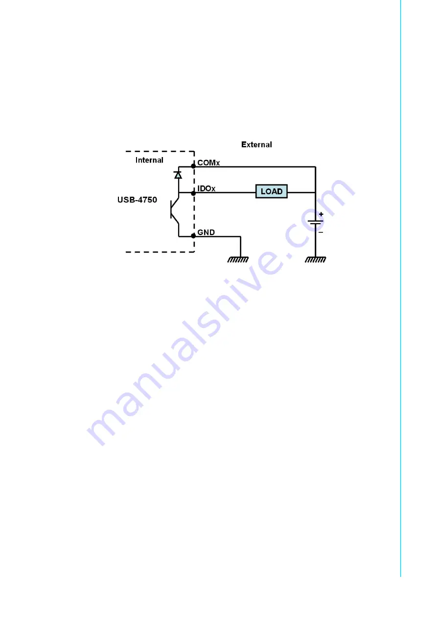
B.2.2
Isolated Digital Output Connections
Each of 8 isolated digital output channels comes equipped with a Darlington transis
-
tor. Groups of 8 output channels share common collectors and integral suppression
diodes for inductive loads. Channels 0 ~ 7 use COM0, and channels 8 ~ 15 use
COM1 as a common pin. If an external voltage (5 VDC - 40 VDC) is applied to an iso
-
lated output channel (IDO 0 ~ IDO 15) while it is being used as an output channel, the
current will flow from the external voltage source to the card. Please ensure that the
current through each GND pin does not exceed 100 mA.
Figure B.2 Isolated Digital Output Connections
Содержание AIIS-3411 Series
Страница 1: ...User Manual AIIS 3411 Machine Vision System Computer ...
Страница 8: ...AIIS 3411 User Manual viii ...
Страница 12: ...AIIS 3411 User Manual xii ...
Страница 13: ...Chapter 1 1 General Introduction This chapter gives background information on the AIIS 3411 series ...
Страница 36: ...AIIS 3411 User Manual 24 ...
Страница 37: ...Chapter 3 3 AMI BIOS Setup ...
Страница 48: ...AIIS 3411 User Manual 36 3 2 2 8 Super IO Configuration Figure 3 11 Super IO Configuration ...
Страница 64: ...AIIS 3411 User Manual 52 ...
Страница 65: ...Chapter 4 4 Software Installation This chapter introduces driver installation ...
Страница 69: ...57 AIIS 3411 User Manual Chapter 4 Software Installation ...
Страница 70: ...AIIS 3411 User Manual 58 ...
Страница 71: ...Appendix A A Programming the Watchdog Timer ...
Страница 79: ...Appendix B B 32 bit DIO Signal Connections ...
Страница 82: ...AIIS 3411 User Manual 70 ...
Страница 83: ...Appendix C C Exploded Diagram Parts List ...
Страница 84: ...AIIS 3411 User Manual 72 C 1 Exploded Diagram Figure C 1 Exploded Diagram ...