Brother KE100 Motor Drive, User Manual
The Brother KE100 Motor Drive user manual is available for free download at manualshive.com. This comprehensive manual provides step-by-step instructions and guidelines for operating and maintaining the KE100 Motor Drive effortlessly. Get your copy today and harness the full potential of this exceptional product.
Share
Download


Reviews:
No comments
Related manuals for KE100 Motor Drive

Panafax UF-8000
Brand: Panasonic Pages: 187
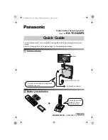
KX-TCD820FX
Brand: Panasonic Pages: 6
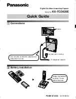
KX-TCD820E
Brand: Panasonic Pages: 6

DP-180
Brand: Panasonic Pages: 65
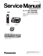
KX-TG234SK
Brand: Panasonic Pages: 99

240 PB
Brand: Bandit Pages: 10

Autopax PAX600H
Brand: Quasar Pages: 148

AutoHybrid
Brand: JK Audio Pages: 16

9045218
Brand: Tennant Pages: 6

BR 90 R
Brand: Kärcher Pages: 15

733R-5
Brand: Consew Pages: 36

Fax 680 MP
Brand: Ricoh Pages: 84

MS-202
Brand: DS Produkte Pages: 68

GBC Ricoh StreamPunch Ultra
Brand: ACCO Brands Pages: 11

AMS-221EHL
Brand: JUKI Pages: 235

BB 700
Brand: Husqvarna Pages: 80
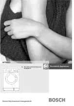
wfd2473
Brand: Bosch Pages: 24

TF MEGA-M
Brand: Hefter Systemform Pages: 80


