Ricoh Fax 680 MP, Service Manual
The Ricoh Fax 680 MP is a high-performance fax machine designed to streamline your office communication. With its advanced features and efficient functionality, you can now send and receive faxes effortlessly. Ensure smooth operations by accessing the comprehensive Service Manual that you can easily download for free from our website.
Share
Download


Reviews:
No comments
Related manuals for Fax 680 MP

Sparrow
Brand: Daedalus Pages: 20

1600P PROFESSIONAL -
Brand: Janome Pages: 29
MARCY PLATINUM MS-91
Brand: MPEX Pages: 11

Easy Melt Air 1G
Brand: Ultraflex Pages: 22

BD 44 180
Brand: Kärcher Pages: 54

QC-S300
Brand: Horizon Fitness Pages: 70

9045218
Brand: Tennant Pages: 6

FAX LAB 650
Brand: Olivetti Pages: 16

4182i 100 Series
Brand: Minerva Boskovice Pages: 38

FM 910
Brand: Olympia Pages: 22

Sew Green
Brand: ELNA Pages: 48

1200D
Brand: Janome Pages: 91

AS6690T
Brand: Viper Pages: 2
G3 Series
Brand: Sealey Pages: 3
SA2501
Brand: Sealey Pages: 4
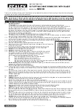
SM180B
Brand: Sealey Pages: 4
SM355B
Brand: Sealey Pages: 4
GSA26
Brand: Sealey Pages: 4


