JUKI AMS-221EHL, Manual
The JUKI AMS-221EHL is a top-of-the-line sewing machine designed for professional garment makers. With its advanced features and user-friendly interface, this machine allows for precise stitching and effortless creation of intricate designs. Download the free user manual from our website to unleash the full potential of this remarkable product.
Share
Download


Reviews:
No comments
Related manuals for AMS-221EHL
KX-TGK220E
Brand: Panasonic Pages: 16
KX-TG9472B
Brand: Panasonic Pages: 64
KX-TG9331T
Brand: Panasonic Pages: 60

47W70
Brand: Singer Pages: 8

VULKAN PRO
Brand: Algam Lighting Pages: 16
MARCY PLATINUM MS-91
Brand: MPEX Pages: 11

i-Qon
Brand: Ash Pages: 30
Argenta
Brand: Azkoyen Pages: 88

QK32
Brand: Windsor Pages: 30

T-Fax 2420
Brand: T-COM Pages: 6

TB 1280
Brand: Olympia Pages: 104

AMS-229B
Brand: JUKI Pages: 68

IP-100
Brand: JUKI Pages: 79

L 79485 FL
Brand: AEG Pages: 28
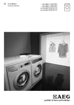
LAVAMAT 69470FL
Brand: AEG Pages: 28

10
Brand: Kenmore Pages: 90

A230
Brand: Panasonic Pages: 377

RBE-2000
Brand: Royal Sovereign Pages: 36


