21
ACP-1320BP User Manual
Chapter 4
A
larm Board
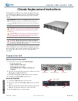
Figure 4.3 Thermal sensor module
Users can set up to 8 thermal sensors. The default sensor I.D. number is 1. Users
can refer to Table 4.13 to set the sensor I.D. number by adjusting the switch, SW1, on
the sensor module.
Table 4.12: CN1 & CN2, Temperature sensor connector
Pin 1
+5 V
Pin 3
T_SDAT
Pin 2
T_SCLK
Pin 4
GND
Table 4.13: SW1, Thermal sensor I.D. number setting
Sensor I.D. No.
SW 1 -1
SW 1 - 2
SW 1 - 3
SW 1 - 4
1 (default)
OFF
OFF
OFF
ON
2
OFF
OFF
ON
ON
3
OFF
ON
OFF
ON
4
OFF
ON
ON
ON
5
ON
OFF
OFF
ON
6
ON
OFF
ON
ON
7
ON
ON
OFF
ON
8
ON
ON
ON
ON
Содержание ACP-1320BP
Страница 1: ...User Manual ACP 1320BP 1U high Rackmount IPC Chassis with Dual SATA Storage Trays...
Страница 10: ...ACP 1320BP User Manual x...
Страница 13: ...Chapter 1 1 General Information...
Страница 16: ...ACP 1320BP User Manual 4 1 5 Dimensions of ACP 1320BP Figure 1 1 Dimensions of ACP 1320BP...
Страница 17: ...Chapter 2 2 System Setup...
Страница 23: ...Chapter 3 3 Operation...
Страница 29: ...Chapter 4 4 Alarm Board...
Страница 34: ...ACP 1320BP User Manual 22...
Страница 35: ...Appendix A A Exploded Diagram...
Страница 37: ...Appendix B B Backplane Options...
Страница 39: ...27 ACP 1320BP User Manual Appendix B Backplane Options...