Supero SC835 Chassis Series, User Manual
The Supero SC835 Chassis Series is a high-performance server chassis designed for optimal airflow and cooling. To set up and configure your chassis, be sure to download the free User Manual from manualshive.com to ensure proper installation. Get the most out of your chassis with the comprehensive manual.
Share
Download


Reviews:
No comments
Related manuals for SC835 Chassis Series

AISWITCH
Brand: Kentrox Pages: 306
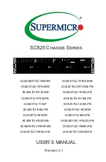
SC825 Series
Brand: Supermicro Pages: 98

CTP150
Brand: Juniper Pages: 22

9C114
Brand: Cabletron Systems Pages: 26

RMC-1E
Brand: AIC Pages: 20

CHAMELEON GN40
Brand: Wisi Pages: 8

VelocityKVM T-4200 Series
Brand: Thinklogical Pages: 23

MERCURY HELIOS 3
Brand: OWC Pages: 11

Mercury Helios 2
Brand: OWC Pages: 12

FL10.1
Brand: FUNAI Pages: 72
phenom mini-itx
Brand: BitFenix Pages: 18
Total Access 3000
Brand: ADTRAN Pages: 32
1181001L1
Brand: ADTRAN Pages: 38


