


ACP-1320BP User Manual
18
4.1
Introduction
The alarm board is located in the middle section, between the driver bay and the
power supply. The alarm board gives an audible alarm when:
!
A cooling fan fails
!
Chassis internal temperature is too high
To stop the alarm beep, simply press the Alarm Reset button on the front panel, then
take the necessary actions to remedy the situation.
4.2
Alarm Board Layout
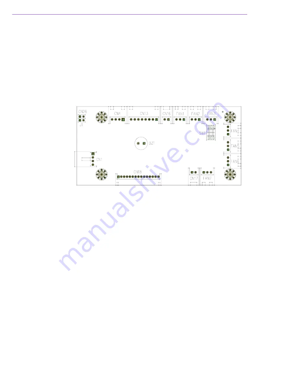
The layout and detailed specification of the alarm board are given below:
Figure 4.1 Alarm board layout
4.3
Alarm Board Specifications
Input Power:
+5 V, +12 V
Input Signals:
!
7 fan connectors
!
One ‘thermal sensor’ connector (supports up to 8 thermal sensors in series)
!
One ‘power good’ input
!
One ‘alarm reset’ input
!
One ‘voltage signal’ connector (connect from the backplane, and support six
voltages:
±
12 V,
±
5 V, +3.3V, +5 Vsb)
!
One ‘hard disk LED’ connector (connect from the CPU card or the motherboard)
Output Signals:
!
One ‘LED board’ connector
!
One ‘buzzer’ output
Содержание ACP-1320BP
Страница 1: ...User Manual ACP 1320BP 1U high Rackmount IPC Chassis with Dual SATA Storage Trays...
Страница 10: ...ACP 1320BP User Manual x...
Страница 13: ...Chapter 1 1 General Information...
Страница 16: ...ACP 1320BP User Manual 4 1 5 Dimensions of ACP 1320BP Figure 1 1 Dimensions of ACP 1320BP...
Страница 17: ...Chapter 2 2 System Setup...
Страница 23: ...Chapter 3 3 Operation...
Страница 29: ...Chapter 4 4 Alarm Board...
Страница 34: ...ACP 1320BP User Manual 22...
Страница 35: ...Appendix A A Exploded Diagram...
Страница 37: ...Appendix B B Backplane Options...
Страница 39: ...27 ACP 1320BP User Manual Appendix B Backplane Options...