background image

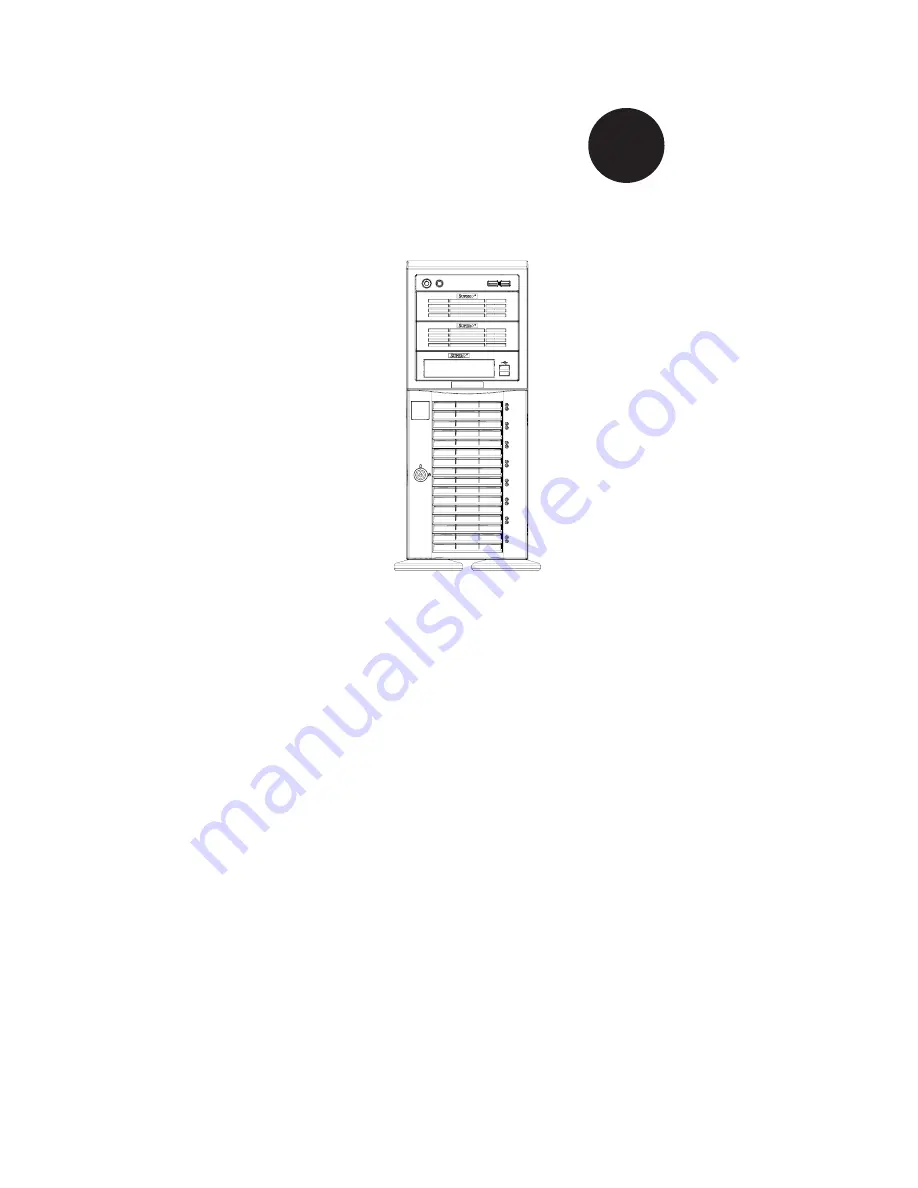
SC743 Chassis Series

SC743TQ-865B-SQ

SC743TQ-865(B)

SC743TQ-R760(B)

SC743S2-R760(B)

SC743S1-R760(B)

SC743T-R760(B)

SC743i-R760(B)

SC743TQ-650(B)

SC743T-665(B)

SC743S1-650(B)

SC743S2-650(B)

SC743i-650(B)

SC743T-650(B)

SC743T-645(B)

SC743S1-645(B)

SC743i-645(B)

SC743i-500B

SC743T-500B

SC743i-465(B)

USER’S MANUAL

1.2c


S

UPER

®

Summary of Contents for SC743i-465

Page 1: ...743TQ R760 B SC743S2 R760 B SC743S1 R760 B SC743T R760 B SC743i R760 B SC743TQ 650 B SC743T 665 B SC743S1 650 B SC743S2 650 B SC743i 650 B SC743T 650 B SC743T 645 B SC743S1 645 B SC743i 645 B SC743i 5...

Page 2: ...photocopied reproduced translated or reduced to any medium or machine without prior written consent IN NO EVENT WILL SUPERMICRO BE LIABLE FOR DIRECT INDIRECT SPECIAL INCIDENTAL SPECULATIVE OR CONSEQU...

Page 3: ...ould be performed by experienced technicians only Supermicro s SC743 chassis features a unique and highly optimized design The chassis is equipped with a 465 500 645 650 665 760 or 865 Watt power supp...

Page 4: ...shields and other components Chapter 4 Chassis Setup and Maintenance Follow the procedures given in this chapter when installing or removing components or reconfiguring your chassis Chapter 5 Rack In...

Page 5: ...omponents 3 1 Chassis 3 1 Mounting to a Rack Optional 3 1 Power Supply 3 1 3 3 Where to get Replacement Components 3 2 3 4 Front LED Panel 3 2 3 5 Control Panel Buttons 3 3 3 6 Control Panel LEDs 3 3...

Page 6: ...3 Preparing for Setup 5 1 Choosing a Setup Location 5 1 Rack Precautions 5 2 General Server Precautions 5 2 Rack Mounting Considerations 5 3 Ambient Operating Temperature 5 3 Reduced Airflow 5 3 Mech...

Page 7: ...n 8x SAS SATA 7x FF 865W SC743TQ 865B DP Xeon 8x SAS SATA 7x FF 865W SC743TQ R760 SC743TQ R760B DP Xeon 800 FSB 8x SAS SATA 7x FF 760W SC743S2 R760 SC743S2 R760B DP Xeon 800 FSB 8x SCA Dual Channel 7x...

Page 8: ...8x Fixed 7x FF 500W SC743T 500B UP DP Xeon AMD 8x SATA 7x FF 500W SC743i 465 SC743i 465B UP DP Xeon AMD 8x Fixed 7x FF 465W Low Noise 1 3 Where to get Replacement Components Although not frequently y...

Page 9: ...dress Super Micro Computer B V Het Sterrenbeeld 28 5215 ML s Hertogenbosch The Netherlands Tel 31 0 73 6400390 Fax 31 0 73 6416525 Email sales supermicro nl General Information support supermicro nl T...

Page 10: ...ust be mailed when service is complete For faster service RMA authorizations may be requested online http www supermicro com support rma Whenever possible repack the chassis in the original Supermicro...

Page 11: ...If the chassis itself shows damage file a damage claim with carrier who delivered your system Decide on a suitable location for the rack unit that will hold that chassis It should be situated in a cle...

Page 12: ...When working around exposed electrical circuits another person who is fa miliar with the power off controls should be nearby to switch off the power if necessary Use only one hand when working with p...

Page 13: ...neckties and unbuttoned shirt sleeves which can come into contact with electrical circuits or be pulled into a cooling fan Remove any jewelry or metal objects from your body which are excellent metal...

Page 14: ...nto contact with your clothing which may retain a charge even if you are wearing a wrist strap Handle a board by its edges only do not touch its components peripheral chips memory modules or contacts...

Page 15: ...5 25 peripheral bays Up to eight 3 5 hard drives Up to seven expansion cards For the latest shipping lists visit our Web site at http www supermicro com Mounting to a Rack Optional The SC743 can be p...

Page 16: ...Integrators Resellers A list of Supermicro Authorized Distributors System Integrators Resellers can be found at http www supermicro com Click the Where to Buy link 3 4 Front Control Panel The followi...

Page 17: ...before servicing Reset The reset button is used to reboot the system 3 6 Control Panel LEDs The control panel located on the front of the SC743 chassis has five LEDs These LEDs provide you with criti...

Page 18: ...fan failure When continuously on not flashing it indicates an overheat condition which may be caused by cables obstructing the airflow in the system or the ambient room temperature being too warm Che...

Page 19: ...3 5 Chapter 3 Chassis Components Power Fail Indicates a power failure to the system s power supply units...

Page 20: ...SC743 Chassis Manual 3 6 Notes...

Page 21: ...3i 650 SC743i 645 SC743i 500 and SC743i 465 must be powered down and the power supply must be discon nected from the backplane prior to removing the hard drives See the instructions in this section fo...

Page 22: ...easy identification 3 Warning Use a grounded wrist strap designed to prevent static discharge when handling compo nents After completing the above steps you can remove the chassis cover and install c...

Page 23: ...r Accessing and Installing Hard Drives Unlock and open the drive tray door as shown 1 Press the release tab located on the drive tray door to release the drive tray 2 from its locking position Lift up...

Page 24: ...ed in section 4 2 4 Disconnect the wiring which the hard drive to either the motherboard or the 5 expansion card of the motherboard depending upon your chassis model Unlock and open the drive tray doo...

Page 25: ...t a hard drive into the hard drive tray 3 Replace the screws which were set aside earlier 4 Install the hard drive into the chassis 5 Push down the release tab over the newly installed hard drive 6 Cl...

Page 26: ...ll three 3 5 fixed hard drives in a 5 25 peripheral drive bay or install five hot swappable hard drives by using an M35 mobile rack inside the storage module Tower Configuration Rotate the chassis int...

Page 27: ...locked into position 5 Figure 4 6 Installing 5 25 Devices into the Storage Module Configuring the Storage Module for 3 5 Devices with a Mobile Rack Remove the storage module from the chassis 1 Remove...

Page 28: ...rear fan and does not require an air shroud This chassis does not require an air shroud In the unlikely event that a system fan needs to be replaced be sure to specify the SQ model number when orderi...

Page 29: ...the rear of the chas 1 sis Push the release tab down to unlock the fan Once the fan is unlocked tip it forward and out of the chassis 2 When replacing the rear chassis fan push the fan back into the...

Page 30: ...with a specialized air shroud to accomodate the super quiet front and rear fans Be sure to specify air shroud model number MCP 310 74301 ON upon arrival in the unlikely event that the air shroud needs...

Page 31: ...omponents Processor s Mounting holes Retention brackets Type A 6 32 screws included in the chassis accessory kit Obtain the following parts for the motherboard being used These should be included with...

Page 32: ...ht pounds of torque per square inch when tightening down the motherboard Replace the middle and rear system fans as directed in section 4 6 8 Replace the air shroud as directed in section 4 7 9 Warnin...

Page 33: ...herboard expansion cards such as PCI cards may be in stalled into the chassis Installing Expansion Cards Locate the release tab on the top of the expansion card bracket 1 Gently apply pressure on the...

Page 34: ...emove the 3 bracket from the chassis After removing the bracket from the chassis expansion cards may be in 4 stalled in the bracket Install the bracket with the newly installed expansion card back int...

Page 35: ...pplies can only be serviced by a qualified manufacturer s technician 465 500 645 650 665 and 865 Watt Power Supplies The 465 500 645 650 665 and 865 Watt power supplies offer different features but ar...

Page 36: ...power supplies Installing the Power Supply Unplug the AC power cord from the power supply 1 Push the release tab on the left side of each power supply to release it from 2 the locked position Once rel...

Page 37: ...ccessing the Interior Space Remove the two screws as shown below and set them aside for future use 1 Remove the three screws on the bottom of the bracket between the back 2 plane and the mideplane Use...

Page 38: ...ht click on the 1 My Computer icon and choose Properties Select the 2 Hardware tab and click on Device Manager Open 3 System Devices or browse to the location of GEM318 Right click on this device and...

Page 39: ...se and select uninstall If two such question marks are present uninstall both Select the 4 Action tab and click on Scan for Hardware Changes The Hard ware Wizard program should start up Click the Next...

Page 40: ...SC743 Chassis Manual 4 20 Notes...

Page 41: ...n a clean dust free area that is well ventilated Avoid areas where heat electrical noise and electromagnetic fields are generated You will also need it placed near a grounded power outlet Be sure to r...

Page 42: ...a time Extending two or more simul taneously may cause the rack to become unstable General Server Precautions Review the electrical and general safety precautions that came with the com ponents you ar...

Page 43: ...nical Loading Equipment should be mounted into a rack so that a hazardous condition does not arise due to uneven mechanical loading Circuit Overloading Consideration should be given to the connection...

Page 44: ...ling the Inner Chassis Rails Locate the pair of inner rails and two sets of screws 6 screws per set that 1 are included in the shipping package Remove the chassis feet and top cover 2 Align the inner...

Page 45: ...the middle rail and secure them 2 with the screws as shown Install a set of outer rail assemblies to each side of the rack and secure them 3 with the screws provided Check that both sets of inner rail...

Page 46: ...SC743 Chassis Manual 5 6 Figure 5 3 Mounting the Chassis into a Rack Inner Rails Outer Rail Assemblies...

Page 47: ...Cable 9 Two drop SCSI ultra 320 cable CBL 0087 Cable 20 Round 16 pin to 16 pin front panel ribbon cable CBL 0084 Cable 6 Split converter cable CBL 0063L Cable 20 SCSI cable CBL 0062L Cable 7 9 12V 8 p...

Page 48: ...on cable CBL 0084 Cable 6 Split converter cable CBL 0157L Cable 15 8 8 pin to 8 pin ribbon cable for SGPIO supports up to 4 drives CBL 0216L Cable 8 26 210mm 4 pin to 4 pin fan power cable SC743T Seri...

Page 49: ...pin CBL 0059 7 9 20 CM 8 pin CBL 0062 7 9 20 CM 4 pin CBL 0060 7 9 20 CM Front Panel to the Motherboard The SC743 chassis includes a cable to connect the chassis front panel to the motherboard If your...

Page 50: ...M4 x 4 mm 0 157 RAIL Round head M4 x 4 mm 0 157 Flat head M5 x 12 mm 0 472 Washer for M5 DVD ROM CD ROM and FLOPPY DRIVE Flat head 6 32 x 5 mm 0 197 Pan head 6 32 x 5 mm 0 197 Round head M3 x 5 mm 0...

Page 51: ...x lists power supply specifications for your chassis system 465W MFR Part PWS 465 PQ Rated AC Voltage 100 240V 60 50Hz 6 3 Amp 5V standby 3 Amp 12V 35 Amp 5V 20 Amp 3 3V 15 Amp 12V 0 5 Amp 500W MFR Pa...

Page 52: ...54 0 Amp 5V 30 0 Amp 3 3V 24 Amp 12V 0 5 Amp 650W MFR Part PWS 0056 Rated AC Voltage 100 240V 50 60Hz 11 5Amp 5V standby 4 0 Amp 12V 46 Amp 5V 30 0 Amp 3 3V 30 0 Amp 12V 0 6 Amp 645W MFR Part PWS 006...

Page 53: ...WS 0056 Rated AC Voltage 100 240V 50 60Hz 14 8 Amp 5V standby 3 5 Amp 12V 50 0 Amp 5V 36 0 Amp 3 3V 36 0 Amp 12V 1 0 Amp 865W MFR Part PWS 865 PQ Rated AC Voltage 100 240V 50 60Hz 12 6 Amp 5V standby...

Page 54: ...SC743 Chassis Manual B 4 Notes...

Page 55: ...320 160 hard drives providing configuration flexibility and maximum data integrity If your system is running on a Windows operating system refer to section 4 13 of this manual for instructions on inst...

Page 56: ...washer head screws Eight 8 counts of M3 washer head screws Eighteen 18 counts of pan head screws For CSE M34T only Serial ATA backplane CSESATA M34 Four 4 Serial ATA cables CBL 0044 Serial ATA LED cab...

Page 57: ...ctions Use the instructions listed in this manual to use the mobile rack independent of a chassis The pictures or graphics shown in this user s guide were based upon the latest PCB revision available...

Page 58: ...tings for the CSE M34S SCSI JP18 JP21 JP24 JP14 JP25 Jumper Description Setting JP14 Delay start Closed Enable Open Disable default JP18 Bumper Reset Closed Enable Open Disable default JP21 SCSI Termi...

Page 59: ...CBL 0057 SATA LED Cable JP27 Common Act In Act 1 Closed Enable Open Disable default JP28 Fan Sense 1 2 Enabled if a fan is not present the alarm will sound default 2 3 Disabled JP29 Common Act In Act...

Page 60: ...ns for the CSE M35T SATA JP18 JP25 Channel 2 Channel 3 Channel 4 Channel 1 JP28 ACT2 ACT3 ACT4 COM Key JP26 ACT1 Activity LEDs Pin Definitions JP26 Act LED1 Channel 1 Act LED2 Channel 2 Act LED3 Chann...

Page 61: ...ally on the drives See the previous section for SCSI ID jumper settings SCSI termination is enabled by default on the SCSI backplane 2 Accessing Hot Swappable Drives Push the release button located be...

Page 62: ...shown with the screws provided 2 Figure C 5 Installing the Drive into the Drive Tray Warning Enterprise level hard disk drives are recommended for use in Supermicro chassis and servers For informatio...

Page 63: ...fications Accessing the Backplane Remove the screws located on the back of the mobile rack unit as shown 1 Pull out the rear fan bracket 2 Remove the screws securing the backplane 3 1 1 Figure C 6 Acc...

Page 64: ...SC743 Chassis Manual C 10 Notes...

Page 65: ...guration flexibility and maximum data integrity If your system is running on a Windows operating system refer to section 4 11 of this manual for instructions on installing the appropriate drivers requ...

Page 66: ...ve 5 1 host receptacle connectors SATA hot swappable hard drives CSE M35T 1 only Cooling Subsystem Monitoring One 1 9cm exhaust fan Fan fail detection LED and alarm Overheat LED indication Drive fail...

Page 67: ...for the CSE M35S SCSI Mobile Rack Jumper Description Setting JP18 Bumper Reset Closed Enable Open Disable Default JP21 SCSI Termination Closed Enable Open Disable Default JP24 SCSI ID Selection 1 2 SC...

Page 68: ...umper Locations SATA JP28 JP25 JP18 Channel 1 Channel 2 ACT5 FAN Channel 3 Channel 4 Channel 5 ACT6 ACT7 ACT8 ACT1 ACT2 ACT3 ACT4 COM Pin 1 Pin 1 Jumper Description Setting JP18 Buzzer Reset Closed En...

Page 69: ...ne Do not set IDs manu 1 ally on the driver See the previous section for SCSI ID jumper settings SCSI termination is enabled by default on the SCSI backplane 2 Accessing the Hot Swappable Drives Acces...

Page 70: ...ard drive tray into the mobile storage rack 6 3 Figure D 4 Removing the Hard Drives 6 5 4 Figure D 5 Installing the Hard Drives into the Drive Tray Warning Enterprise level hard disk drives are recomm...

Page 71: ...ly pull the fan away from the back of the mobile storage rack 2 Note For the SC942 chassis the CSE M35 rear exhaust fan should not be used Instead the hot swappable 120mm chassis fans included with th...

Page 72: ...Removing the Backplane Remove the screw located on the side of the storage module as shown 1 Pull the rear bracket out of the storage module 2 1 2 Figure D 8 Removing the Rear Bracket Screw Figure D...

Page 73: ...D 9 Apppendix D CSE M35S CSE M35T1 Mobile Rack Specifications Remove the backplane 3 3 Figure D 10 Removing the Backplane...

Page 74: ...SC743 Chassis Manual D 10 Notes...

Page 75: ...to prevent static discharge Touch a grounded metal object before removing a component from the antistatic bag Handle the backplane by its edges only do not touch its components peripheral chips memory...

Page 76: ...aphics shown in this manual E 4 Introduction to the SAS 743TQ Backplane The SAS 743TQ backplane has been designed to utilize the most up to date tech nology available providing your system with reliab...

Page 77: ...e Connector JP46 2 Chip MG9072 3 Power Connectors 4 pin JP10 4 and JP13 ACT IN JP26 5 Sideband Connector 2 JP52 6 Sideband Connector 1 JP51 7 I 8 2 C Connector 2 JP45 I 9 2 C Connector 1 JP44 SAS Port...

Page 78: ...he MG9072 is an enclosure management chip that supports the SES 2 controller and SES 2 protocols Backplane Main Power 4 Pin Connector Pin Definition 1 12V 2 and 3 Ground 4 5V 4 Backplane Main Power Co...

Page 79: ...3 GND SB2 6 GND SB3 5 SDA SB1 8 Backplane ID SB7 7 SCL SB0 10 No Connec tion 9 No Connec tion 8 and 9 I2 C Connectors The I2 C connectors designated JP44 and JP45 are used to monitor HDD activity and...

Page 80: ...6 H3 M90 M 9 1 M96 M97 MM2 MM3 SAS743TQ REV 3 00 R SUPER pb 12V 12V GND GND GND GND 5V 5V 48 1 16 64 49 2 M 7 1 M75 M86 M87 6 H3 M90 M 9 1 M96 M97 MM3 SAS743TQ REV 3 00 R SUPER pb JP50 12V GND GND GND...

Page 81: ...rcuit board Note On two pin jumpers Closed means the jumper is on and Open means the jumper is off the pins Connector Pins Jumper Setting 3 2 1 3 2 1 Jumper Settings Jumper Jumper Settings Note JP18 O...

Page 82: ...ler ID 1 JP34 1 2 ID 0 1 2 Backplane ID 1 JP36 2 3 1 2 Controller ID 2 JP37 2 3 ID 1 1 2 Backplane ID 2 JP38 Closed Open I2 C Reset 2 JP40 Open Closed I2 C Reset SDOUT 1 JP41 Open Closed I2 C Reset SD...

Page 83: ...cation D3 On Overheat drive failure LED indicator Red light flashing Buzzer On if activated Front LED Indicators 12V 12V GND GND GND GND 5V 5V 48 1 16 64 49 H12 H 7 M 7 1 M75 M86 M87 H5 H6 H3 M90 M 9...

Page 84: ...SAS SATA HHD 4 SAS 5 SAS SATA HHD 5 SAS 6 SAS SATA HHD 6 SAS 7 SAS SATA HHD 7 Rear LED Indicators Rear LED Hard Drive Activity Failure LED SAS 0 D12 D5 SAS 1 D13 D6 SAS 2 D14 D7 SAS 3 D15 D8 SAS 4 D18...

Page 85: ...prevent static discharge Touch a grounded metal object before removing a component from the antistatic bag Handle the backplane by its edges only do not touch its components peripheral chips memory m...

Page 86: ...cs shown in this manual F 4 Introduction to the SATA 743 Backplane The SATA 743 backplane has been designed to utilize the most up to date technol ogy available providing your system with reliable hig...

Page 87: ...24 RST JP25 OH TEMP OPEN 45 C 1 2 50 C 2 3 55 C F 5 Front Connectors and Jumpers 9 8 7 6 2 1 2 1 3 10 1 11 1 12 Overheat Temperature Setting 1 JP25 Power Connectors 4 pin JP10 2 and JP13 ACT_IN 0 7 JP...

Page 88: ...Definitions Pin Definition Pin Definition 1 ACT IN 0 6 ACT IN 4 2 ACT IN 1 7 ACT IN 5 3 ACT IN 2 8 ACT IN 6 4 ACT IN 3 9 ACT IN 7 5 Ground 10 Empty 3 Activity LED Connector The activity LED connector...

Page 89: ...F 2 Front Jumpers 12V 12V GND GND GND GND 5V 5V 48 1 16 64 49 H 7 H5 H3 MM2 SATA743 REV 3 00 R SUPER pb 1 0 2 3 4 6 5 7 ACT IN OH LED JP10 JP13 JP25 JP26 JP18 JP35 BZ1 JP18 BUZZER RESET JP35 GEM24 RS...

Page 90: ...b 1 0 2 3 4 6 5 7 ACT IN OH LED JP10 JP13 JP25 JP26 JP18 JP35 BZ1 JP18 BUZZER RESET JP35 GEM24 RST JP25 OH TEMP OPEN 45 C 1 2 50 C 2 3 55 C D3 Front Panel LEDs LED Normal State Indicator Status D3 OH...

Page 91: ...5 FAIL6 ACT6 FAIL7 ACT7 F 8 Rear Connectors and LED Indicators Rear Connectors Rear SATA Connectors Rear Connector SATA Drive Number SATA 0 SATA HDD 0 SATA 1 SATA HDD 1 SATA 2 SATA HDD 2 SATA 3 SATA H...

Page 92: ...CT 3 D15 SATA HDD 3 ACT 4 D18 SATA HDD 4 ACT 5 D21 SATA HDD 5 ACT 6 D22 SATA HDD 6 ACT 7 D25 SATA HDD 7 Figure F 5 Rear LEDs H4 FAIL0 2 1 0 3 4 5 6 7 J3 J2 J1 J4 J9 J11 J13 J15 ACT0 FAIL1 ACT1 FAIL2 A...

Page 93: ...F 9 Appendix F SATA 743 Backplane Specifications Notes...

Page 94: ...reasonably expected to result in significant injury or loss of life or catastrophic property damage Accordingly Supermicro disclaims any and all liability and should buyer use or sell such products fo...

Reviews: