


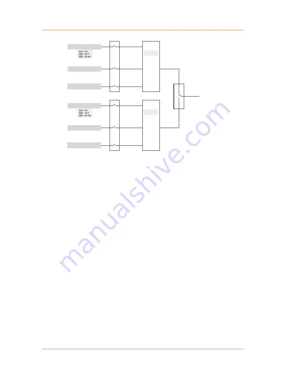
Setpoint configuration
Remote
Total setpoint
Motor potentiometer
Addition
Analog setpoint
Bus setpoint
Setpoint configuration
Local
Motor potentiometer
Addition
Analog setpoint
Bus setpoint
Remote/local switch
Figure 4‑1. Total setpoint
The local analog setpoint, and local motor potentiometer setpoint are used by default.
If an Anybus module is installed, the remote bus setpoint is used by default.
Switching between the local setpoint and the remote setpoint can be controlled using
the Thyro-Touch display, the Thyro-Tool Pro PC software, or the bus
communication. A digital I/O line may also be configured to control the local/remote
switch.
Status Indicators (LEDs)
Errors and faults are indicated by the status LEDs, the fault and limit relays, the
Thyro-Touch display, the Thyro-Tool Pro PC software, and the optional bus
interface.
The unit signals faults in the power controller or load circuit via the
FAULT
LED
and fault relay K1. To identify the location of the fault, select the status line, and read
the fault log via the Thyro-Touch display, the Thyro-Tool Pro PC software, or the
bus interface.
Simultaneously with the fault signal, you can use the
Pulse Lock On/Off
(with
acknowledgement),
Pulse Lock On/Off
(without acknowledgement), or
Regulator
Lock On/Off
(without acknowledgement) configuration to require that pulse
shutdown occur.
The Thyro-PX unit LED status indicators are located on the front panel of the unit.
☞
Important
This manual describes the default configuration. Though these functions are
fully configurable, AE recommends not changing the default configuration.
Advanced Energy
®
Thyro-PX® Power Controller
57010148-00B
Communication Controls
4‑2


