background image

1316-900 Revision AA 

10kW Precision Calorimeter


26 

6  

Appendix A  

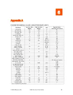
PARAMETER NOMINAL VALUES AND APPROXIMATE LIMITS  

Field Values 

Low Limit Value 

Reading 

High Limit Value 

Reading 

Units 

Expected Values 


(10k watts @ 25°C ambient)


THERMISTOR 

22 

28 

°C  

26° 

RTD_TEMP_PRE 

21.6 

22.4 

°C 

22° 

RTD_TEMP_POST 

21.6 

32 

°C 

31.5° 

THERMOPILE 

0.8 

volts 

0.73 

WATERFLOW_TEMP_LOSS 

0.002 

°C 

SPECIFIC_HEAT 

3.6 

3.8 

J/g-C 

3.75 

GRAVITY 

1.05 

g/cm3 

1.03 

VISCOSITY 

0.5 

mPa-sec 

1.51 

FLOWMETER 

300 

320 

pulses/sec 

310 

K_FACTOR 


pulses/liter 

1239 

FLOWRATE 

4.07 

GPM 

4.055 

FLOW_VOLUME 


cm3/sec  

255 

MASS_FLOWRATE 

250 

275 

gm_sec 

265 

SEEBECK_CONSTANT 


volts/C 

.08 

DELTA_T 

10 

°C 

9.05 

LOAD_EFFICIENCY_FACTOR 


-- 

FRICTIONAL_WATTS 

25 

watts 

20 

RF_PRESSURE_DROP 


psi 

7.5 

TOTAL_PRESSURE_DROP 


psi 

26.04 

INPUT_POWER 

-5 

10000 

watts 

8900-10500 

RF_LOAD_DC_RESISTANCE 

45 

55 

ohms 

49.6 

SERIAL_NUMBER_OF_RF_LOAD 


-- 


REFLECTION_COEFFICIENT 

-- 

0.01 Frequency Dependent 

TRANSMISSION_LOSS_FACTOR 


-- 

0.999 

CAL_FACTOR 

-5 

10000 

watts 

10000 

RF_TRANS_LOSS_FACTOR 


-- 

0.999 

RF_EFFICIENCY_FACTOR 


-- 

0.998 

USER_DEF_FREQ 

500 

MHx 

0 to 500 MHz 

RFCALPOW 

-5 

10000 

watts 

10000 

POWER_ADJ 

-4 

watts 

1.25 

T_PIVOT 

23 

27 

°C 

25 

T_POWER 

-2 

watts/°C 

-1 

USE_PUMP 


-- 

True 

PUMP_SET_FREQ 

44.5 

45 

Hz 

44.8 

PUMP_CONTROL 


-- 

True 

PUMP_FREQ 

44.5 

45 

Hz 

44.8 

PUMP_RPM 

1335 

1350 

rpm 

1344 

FLOWRATE_RPM 

3.95 

4.15 

gpm 

4.055 

FLOWRATE_METER 

3.9 

4.1 

gpm 

n/a = not applicable for model #1316 
 

Содержание 1316

Страница 1: ...10kW Model 1316 Precision Calorimeter User Manual February 2023 1316 900 Revision AA...

Страница 2: ...nformation contained herein Product Usage Statement WARNING READ THIS ENTIRE MANUAL AND ALL OTHER PUBLICATIONS PERTAINING TO THE WORK TO BE PERFORMED BEFORE YOU INSTALL OPERATE OR MAINTAIN THIS EQUIPM...

Страница 3: ...ergy s technical writing staff has carefully developed this manual using research based document design principles However improvement is ongoing and the writing staff welcomes and appreciates custome...

Страница 4: ...lation Environment 10 Check the Location Where the Unit Will Be Installed 11 Typical Equipment List 11 Instrument Connections 12 Chiller Preparation 13 Calibration Preparation and Instrument Setup 15...

Страница 5: ...er v Appendix A 26 Appendix B Service Assistance 27 Returns for Repairs 27 Warranty 27 Warranty Limitations 28 Statement of Calibration 28 Storage and Shipment 29 Drain the calorimeter system of all c...

Страница 6: ...ot designed for operation in explosive environments WARNING DO NOT OPERATE WITHOUT COVERS This device should be operated with all panels and covers in place Operation with missing panels or covers cou...

Страница 7: ...practices or tips for efficiency Terms on Equipment CAUTION indicates a personal injury hazard not immediately accessible as one reads the marking or a hazard to property including the equipment itse...

Страница 8: ...o 5 000 W 27 12 MHz to 40 68 MHz 10W to 4 100 W 40 68 MHz to 60 MHZ 10 W to 2 200 W 60 MHz to 200 MHz 10 W to 1 300 W 200 MHz to 500 MHz With optional 3 1 8 connector5 10 W to 10 000 W 50 to 500 MHz C...

Страница 9: ...factured components S11 Linear Magnitude Typical Typical 0 025 at f 100 MHz and 0 1 at f 100 MHz Typical S11 Linear Mag Performance Optional System Components contact your AE TEGAM representative for...

Страница 10: ...to achieve specifications listed Must use recommended options 4 Assumes proper preparations are followed prior to storage including draining the coolant system 5 Optional 3 1 8 connector may increase...

Страница 11: ...ergy in the form of heat to raise the temperature of a certain mass of liquid by a given amount then conversely if we know the temperature rise and the mass of the liquid we can determine the amount o...

Страница 12: ...ional to the absolute temperature of the coolant but to the difference in temperatures of the coolant streams The entire heated coolant stream is involved in the measurement not just a fraction Since...

Страница 13: ...1316 900 Revision AA 10kW Precision Calorimeter 8 Figure 2a Calorimeter Internal Block Diagram Figure 3a Signal Processing Block Diagram...

Страница 14: ...1316 900 Revision AA 10kW Precision Calorimeter 9 Figure 4a 1316 Cooling System Block Diagram...

Страница 15: ...ter and 1316 388 Chiller will be installed in a rack Item Part Number Model 1316 Precision Calorimeter 1316 300 Technical Operation and Maintenance Manual 1316 841 CD or 1316 900 Printed Chiller Fine...

Страница 16: ...uired to complete the calibration TEGAM 1316A RF High Power Calorimeter TEGAM 1300 912 Voltage Current RF Adapter Assembly Preen AFV 31015 optional model High Power Programmable AC Power Source Zimmer...

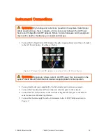
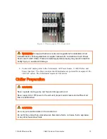
Страница 17: ...or breaker to the AC Power Source See Figure 1 below Figure 1 Voltage Current RF Adapter connections to the AC Power Source WARNING Dangerous voltage current and RF power may be present on the system...

Страница 18: ...nect AC mains power to the Calorimeter AC Power Source 12 kW Chiller and Power Analyzer The Power Analyzer and Calorimeter are powered from separate 200 240 VAC outlets The Calorimeter requires a 20A...

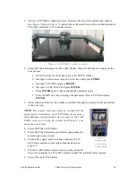
Страница 19: ...ess the UP arrow key to change the parameter value to TRUE and press ENTER 3 Allow sufficient time for the coolant to circulate through the system before proceeding to the next step NOTE The coolant l...

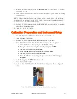
Страница 20: ...ion Preparation and Instrument Setup 1 Install the HPC CAL calibration software on the system workstation 2 Power ON the 12 kW Chiller 3 On the 12 kW Chiller display touch RUN and hold for 2 3 seconds...

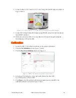
Страница 21: ...ize for no less than two 2 hours before performing the remaining steps of this procedure Calibration 1 Launch the HPC CAL calibration software on the system workstation 2 Click the Test Definition tab...

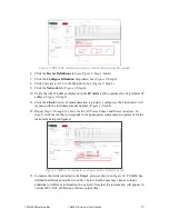
Страница 22: ...on If communication is properly configured the Calorimeter will respond with the instrument model number Figure 9 Step 6 12 Repeat Steps 7 through 11 above for the AC Power Source and Power Analyzer I...

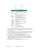
Страница 23: ...ons 14 In the Calorimeter Check group verify the Calorimeter Flow and Flow Meter fields indicate 4 05 GPM 0 03 and that Coolant Temp indicates 22 1 C 0 4 see Figure 11 Step 1 below 15 Optional In the...

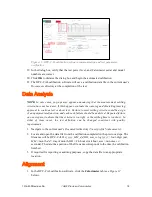
Страница 24: ...t settling criteria could be a sign of an equipment malfunction and each such failure should be analyzed Repeated failure on one step may indicate that the criteria is too tight or the settling time i...

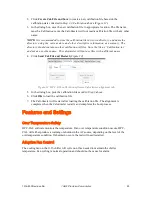
Страница 25: ...not use files with a different name 4 Click Send Cal File and Restart Figure 12 Figure 12 HPC CAL calibration software Calorimeter alignment tab 5 In the dialog box pick the calibration file saved in...

Страница 26: ...by determining the reflection coefficient of the RF load as a function of frequency and compensating for it at the frequency of interest The 1316 automatically compensates for this error term by stori...

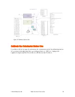
Страница 27: ...er Before Use To calibrate a RF device using the calorimeter the calorimeter must first be calibrated against an AC power meter standard traceable to a governing authority i e NIST etc Configure the e...

Страница 28: ...The life expectancy for the gear pump used inside the chiller is approximately 20 000 hours The following should be performed at intervals of one to six months depending upon usage Remove cover to acc...

Страница 29: ...load resistance values is used by the control feedback algorithm within the CalProg program to set the requested power on the AC power source under automated conditions not under manual operation 2 Ne...

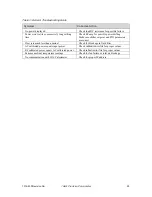
Страница 30: ...er drifting Make sure chiller set point and PID parameters are correct Flow rate much less than nominal Check for blockage in fluid filter AC calibrated power equals input power Check calibration ini...

Страница 31: ..._sec 265 SEEBECK_CONSTANT volts C 08 DELTA_T 0 10 C 9 05 LOAD_EFFICIENCY_FACTOR 1 FRICTIONAL_WATTS 0 25 watts 20 RF_PRESSURE_DROP psi 7 5 TOTAL_PRESSURE_DROP psi 26 04 INPUT_POWER 5 10000 watts 8900 1...

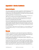
Страница 32: ...ting the problem in the quickest possible manner Use a copy of the Repair and Calibration Service form provided on the next page Once this information is prepared and sent with the instrument to our s...

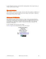
Страница 33: ...tion This instrument has been inspected and tested in accordance with specifications published by TEGAM Inc The calibration of this instrument is traceable to the International System of Units SI thro...

Страница 34: ...ain fluid and or attach to lower coolant drain points of individual chambers that may not have fully drained during the primary draining process There is also a drain valve on the reservoir tank that...

Страница 35: ...nical Contact Phone Number Additional Info R E P A I R I N S T R U C T I O N S E v a l u a t i o n R e p a i r C a l i b r a t i o n C a l i b r a t i o n O n l y R e p a i r o n l y P r o v i d e D a...

Отзывы: