PK-88 OPERATING MANUAL
APPENDIX H
H - 1
PK-88 - 168
APPENDIX H – NET/ROM™ MODIFICATION FOR THE PK-88
To install the NET/ROM firmware into your PK-88, the simple modification described in the follow-
ing steps must be done for proper operation.
NOTE:
Because the PK-88 is not a TNC-2 clone, TheNET™ firmware (and other firmware
designed for TNC-2 clones) will not work in the PK-88. The main reasons are: 1) The
TNC-2 uses hardware dip switches for selecting baud rates, where as the PK-88
baud rates are software selectable; and 2) The SCC chip in the PK-88 is a Z8530,
while the TNC-2 uses a Z8440 (which are not compatible).
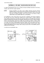
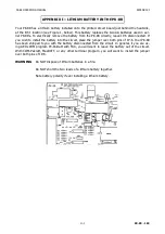
The modification is done in three steps. First, move JP-7 to position B. This jumper is located in
the front left corner of the circuit board, between IC21 and IC22 (Figure 1, below). Position B
means that the small plug is on the center pin and the pin closest to the outside edge of the PCB.
Secondly, solderjump the two halves of JP-8 together and do the same for JP-9. These are actually
lands on the circuit board, and they are located near the serial port (Figure 2, below). Finally,
touch a well-grounded metal object in your shack to discharge any static you may have built up in
your fingers, and, using a small flatbladed screwdriver, gingerly remove the firmware chip (IC15)
from its socket, being careful not to pry the socket from the board itself. once this is done, simply
install the NET/ROM chip into the empty socket, making sure the notch on the EPROM points to-
wards the rear of the PK-88.
Your PK-88 is now a NET/ROM node!
Содержание PK-88
Страница 1: ......
Страница 154: ...PK 88 OPERATING MANUAL APPENDIX D D 1 PK 88 154 APPENDIX D SCHEMATIC and PARTS PICTORIAL...
Страница 155: ...PK 88 OPERATING MANUAL APPENDIX D D 2 PK 88 155...


