PK-88 OPERATING MANUAL
APPENDIX C
C - 1
PK-88 - 152
APPENDIX C – TTL SERIAL INTERFACE HEADER INSTALLATION
The PK-88 comes from the factory configured for RS-232 voltage levels on the 25-pin serial com-
munication port. This is the most popular and indeed the safest way to connect your PK-88 to a
terminal or computer. If your computer has an RS-232C compatible serial interface, then you do
not need to bother with the following TTL information.
Not all computers support RS-232 voltage levels on their serial interfaces which can be a problem
if your computer supports only TTL (0 and 5 Volt) voltage levels. Many of these computers such as
the Commodore 64 and 128 have RS-232 adapters available that will convert the computer's TTL
levels to those compatible with RS-232C.
We recommend that you use an RS-232 level converter if one is available for your computer. If you
have no way of making the computer produce RS-232 levels, then the following instructions de-
scribe how to make the PK-88 compatible with TTL voltage levels.
Included with the PK-88 are two 14-pin DIP headers that allow the PK-88 to generate and accept
TTL (0 and 5 Volt) voltage levels on the 25-pin serial interface connector. To enable TTL operation
of the serial interface, two socketed IC chips must be removed from the PK-88 and the two in-
cluded DIP headers installed in their place.
This procedure may be accomplished as follows:
NOTE:
When working on any electronic equipment, the work area should be as static free
as possible. Try to avoid working in carpeted areas as rugs increase the chance your
body will acquire a static charge. It is also a good idea to discharge any static you
may have acquired by touching a grounded metal appliance before opening the TNC
or working on any internal components.
1. Remove power and all other connections from the PK-88.
2. Open the PK-88 by removing the 4 screws that hold the top chassis in place.
3. Carefully remove the PK-88 top chassis and orient the PK-88 so the rear of the unit faces to the
left.
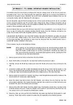
4. Locate IC4 (1489) and IC5 (1488) immediately behind the 25-pin Serial I/O Connector on the
rear of the PK-88 Printed Circuit Board as shown in figure B1. These are the RS-232 line driv-
er/receiver chips that provide/accept the RS-232 voltage levels on the serial interface.
5. Remove both IC4 and IC5 by carefully inserting a small straight-blade screwdriver between the
socket and the IC and prying upward gently.
6. Open the plastic bag that contains the DIP Headers, and remove the one that has only two
wire jumpers attached. This header should be inserted into socket IC4 such that both wires are
closest to the rear of the PK-88 as shown below.
7. Remove the other DIP Header from the plastic bag. This Header should have 3 jumper wires
soldered between the pins. Insert this Header into socket IC5 such that the side that has only
one jumper wire on it is towards the PK-88 power switch.
8. Place the chips you removed from the PK-88 into the plastic bag that held the Headers for safe
keeping. These chips will be needed to restore RS-232 capability to the PK-88 if desired.
Содержание PK-88
Страница 1: ......
Страница 154: ...PK 88 OPERATING MANUAL APPENDIX D D 1 PK 88 154 APPENDIX D SCHEMATIC and PARTS PICTORIAL...
Страница 155: ...PK 88 OPERATING MANUAL APPENDIX D D 2 PK 88 155...

