NetVanta 1531/1534/1544 Series
Physical Descriptions
61702590G1-34H
Copyright © 2019 ADTRAN, Inc.
11
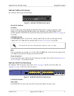
NetVanta 1531 Front Panel Design
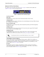
The NetVanta 1531 front panel is shown below.
describes all of the LEDs, and
shows the connector pinouts.
1
2
3
4
5
6
7
8
9
10
STAT
CONSOLE
11
12
NetVanta1531
Figure 1. NetVanta 1531 Front Panel Layout
Front Panel Features
Status LED
The
STAT
LED is located on the left side of the unit and indicates the unit’s status.
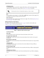
CONSOLE Interface
The
CONSOLE
interface is an EIA-232 serial port (DCE) that provides local management and
configuration (via a DB-9 female connector). Refer to
for pinouts.
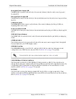
Connection directly to an external modem requires a cross-over cable.
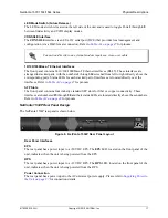
10/100/1000Base-T Ethernet Interfaces
The front panel contains 10 10/100/1000Base-T Ethernet interfaces (RJ-45). These interfaces are
arranged in stacked pairs, with the numbers
1
through
10
screened from left to right directly above the
corresponding ports. Status LEDs for each stacked pair of interfaces are located directly over the
interfaces. Refer to
for pinouts.
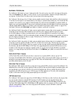
SFP Slots
The front panel contains two industry standard SFP slots for fiber or copper connectivity. The
interfaces numbered
11
and
12
support 1000Base-X SFP modules and their status LEDs are located
directly above the interfaces. Refer to
for pinouts.
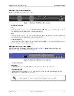
NetVanta 1531 Rear Panel Design
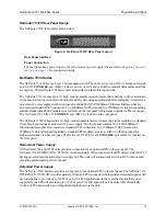
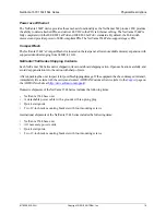
The NetVanta 1531 rear panel is shown below.
AC INPUT
Figure 2. NetVanta 1531 Rear Panel Layout
Rear Panel Interface
Power Connection
The rear panel has a power input to the AC universal power supply. Please refer to


