16
Chassis Overview
Trigger Bus
The trigger bus is an 8-line bus that connects all PXI slots in the
same PCI segment. You can use the trigger bus as an intermodule
synchronization mechanism. PXI modules can transmit trigger or
clock signals to one another through the trigger bus, enabling pre-
cise timed responses to asynchronous external events that the
system is monitoring or controlling.
System Reference Clock
The backplane comes with a PXI 10 MHz system reference clock
(PXI_CLK10). An independent buffer (having source impedance
matched to the backplane and a skew of less than 1 ns between
slots) drives the clock signal generated from a high-precision oscil-
lator to each peripheral slot. You can use this common reference
clock signal to synchronize multiple modules in a PXI chassis.
Содержание 96864-1
Страница 11: ......
Страница 17: ...6 Introduction ...
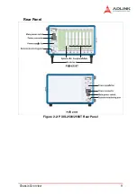
Страница 20: ...Chassis Overview 9 Rear Panel Figure 2 2 PXIS 2508 2558T Rear Panel Foot stand ...
Страница 21: ...10 Chassis Overview Left Panel Figure 2 3 PXIS 2508 2558T Left Panel ...
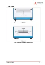
Страница 22: ...Chassis Overview 11 Right Panel Figure 2 4 PXIS 2508 2558T Right Panel ...
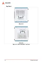
Страница 23: ...12 Chassis Overview Top Panel Figure 2 5 PXIS 2508 2558T Top Panel ...
Страница 24: ...Chassis Overview 13 Base Panel Figure 2 6 PXIS 2508 2558T Base Panel ...
Страница 31: ...20 Installation 5 Fasten the screw on the module front panel then con nect all devices ...
Страница 41: ...30 Installation ...
Страница 53: ...42 Remote Management ...


