


40
Installation and Commissioning Guide
Hercules Package Unit
Installation and Commissioning Guide - Hercules Package Unit
Doc. No.0525-021
Ver. 21 221110
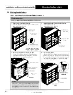
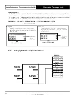
16.06. Fire Trip Installation Procedure
1. Open Access-Door Control Section
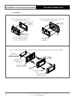
2. Remove Access Panel-Electrical Isolator Section
• Perform steps 1 and 2 of Main Supply Cable Installation
section to gain access to control panel.
CM100
CONTROLLER
CONTROL
INTERFACE
ACCESS
DOOR
CONTROL
ACCESS
DOOR -
CONTROL
1
2
QUARTER
TURN LOCKS
ACCESS PANEL
ELECTRICAL
LOCK
SCREWS
CONTROL
PANEL
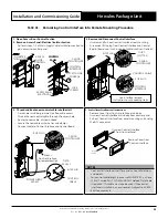
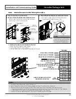
3. Disconnect and Remove Fire Trip Jumper from the
terminals
• Loosen the screws on the Fire Trip Terminals and remove the
Fire Trip Jumper.
Refer to wiring diagram
provided with the unit.
FIRE TRIP
TERMINALS
(RED)
FIRE TRIP
JUMPER
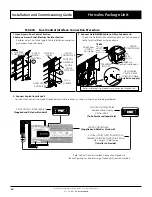
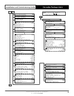
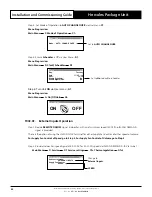
4. Connect a normally closed contact 240V AC 10A minimum to the Fire Trip terminals.
240VAC 10A
Normally Closed
Contact Wires
FIRE TRIP
TERMINALS
FIRE TRIP TERMINALS
TO USE FIRE TRIP REMOVE
JUMPER BETWEEN RED
TERMINALS AND CONNECT TO
A NORMALLY CLOSED CONTACT
240VAC 10A MINIMUM
FT1
FT2
TERM
IFC-1
OFC-1
Содержание HERCULES PKV1400T
Страница 83: ...THIS PAGE WAS INTENTIONALLY LEFT BLANK...


