ActronAir HERCULES PKV1400T Скачать руководство пользователя страница 36

36

Installation and Commissioning Guide

Hercules Package Unit

Installation and Commissioning Guide - Hercules Package Unit

Doc. No.0525-021  

Ver. 21  221110

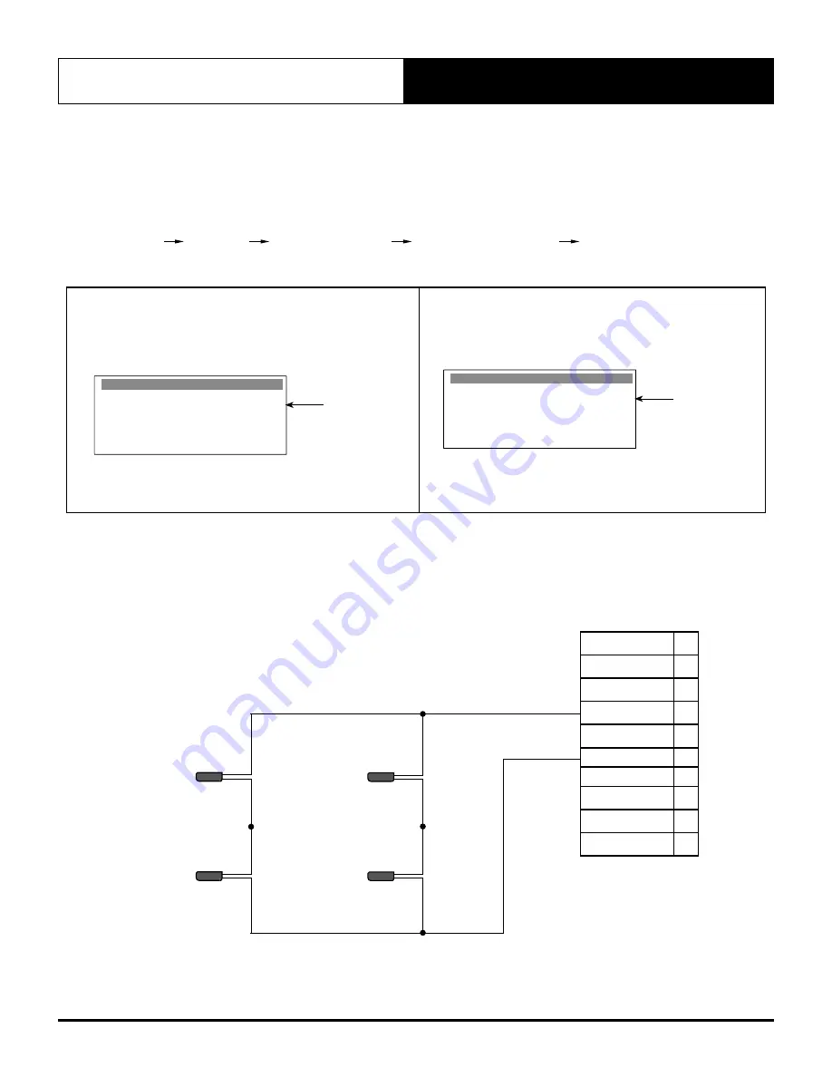
Offset Instructions:

1. Read the return air temperature from the control interface (the installed return air temp sensor is measuring the return 

air temp.

2. Using a different temperature measuring device, measure the actual air temperature next to installed return air sensor.
3. Get the difference to calibrate the installed return air temperature sensor via service menu: 

Main Menu 

 G. Service 

 Gf. Service settings 

  Gfb. Probe Adjustment 

 Gfb3 

(Password Protected)

Example 1:


If the actual measured room temperature is 2.0°C 
higher than control interface reading, then adjust the 
offset to +2.0°C. 

Probe adjust.                       Gfb3

Room  NTC cal:

Supply  NTC cal:

Cond. 1 NTC cal:

Cond. 2 NTC cal:

Outside  NTC cal:

+2.0°C

0.0°C

0.0°C

0.0°C

0.0°C

CP10

Probe Adjustment Display

Enter return 
air temp 
offset here

Example 2:  

If the actual measured room temperature is 2.0°C 
lower than control interface reading, then adjust the 
offset to -2.0°C

Probe adjust.                       Gfb3

Room  NTC cal:

Supply  NTC cal:

Cond. 1 NTC cal:

Cond. 2 NTC cal:

Outside  NTC cal:

-2.0°C

0.0°C

0.0°C

0.0°C

0.0°C

CP10

Probe Adjustment Display

Enter return 
air temp 
offset here

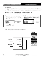
16.01. Averaging Return Air Temperature Sensors

RETURN TEMP

NTC SENSOR 1

RETURN TEMP

NTC SENSOR 3

RETURN TEMP

NTC SENSOR 2

RETURN TEMP

NTC SENSOR 4

15

16
17
18
19

20

21

22
23

24

FAULT COM

FAULT NC

FAULT NO

RETURN AIR 

SENSOR

IN-FAN DEMAND

0 - 10V

GND

REMOTE ON/OFF

DEHUMIDIFY ON

(24VAC)

HEAT ON (24VAC)

24VAC OUT

TERMINAL

Содержание HERCULES PKV1400T

Страница 1: ...anual carefully before installing or operating your air conditioning unit IMPORTANT NOTE Please read this manual carefully before installing or operating your air conditioning unit That s better That...

Страница 2: ...2 Electrical Power Supply Connection 26 13 Maximum Cable Lengths 27 14 Data Cable and RJ12 Plug Preparations 28 15 Wiring Installation 30 15 01 Main Supply Cable Installation Procedure 30 15 02 Contro...

Страница 3: ...oor Fans Outdoor Fans and Compressors Addresses 55 21 Sensors Detail 56 22 EC Indoor Fan Commissioning 57 22 01 Fan Curve PKV1400T 57 22 02 Fan Curve PKV2000T 58 22 03 Re Heat Coil Static Pressure 59...

Страница 4: ...damage to the unit contact ActronAir Customer Care Department immediately on 1300 522 722 to obtain a Goods Return Number Check the unit nameplate to verify the model serial number electrical rated s...

Страница 5: ...alteration by an unqualified technician could result in significant and major damage to the product or property which may render your warranty null and void Such unqualified service could also lead t...

Страница 6: ...and have come to a complete stand still before servicing the equipment Beware of pinch point and sharp edges which can cause cutting injury Secure the fans against accidental contact Always wear appro...

Страница 7: ...ich is locked to the Supply Air Baffles and bolted with a Wing Nut into the inside of the supply air door When the operator opens the door the cable prevents the door from pushing further out Once the...

Страница 8: ...The fans provide superior performance for your comfort at optimum efficiency High efficient variable speed EC motor that uses less energy than traditional belt and pulley system Backward curve impelle...

Страница 9: ...tand health safety storage and disposal requirements Use the approved containment vessels and refer to appropriate safety standards Comply with all applicable transportation standards when shipping re...

Страница 10: ...aces are allocated for these purposes For the connection and location of condensate drain in the unit refer to the drawings and dimensions section of this manual Wiring connections must be in accordan...

Страница 11: ...CESSORIES P K V 2 0 0 0 T D E L T V V E K L W 0 4 1 2 3 4 5 6 7 8 9 10 11 12 13 14 15 16 17 18 19 20 21 22 23 24 V 3 2 1 STANDARD MODEL NOMENCLATURE AIR HANDING OPTIONS EC FANS VARIATION TYPE and NUMB...

Страница 12: ...TT TOP RETURN SR RIGHT SIDE RETURN SL LEFT SIDE RETURN T TOP SUPPLY L LEFT HAND SIDE SUPPLY R RIGHT HAND SIDE SUPPLY B BOTTOM RETURN D DOWN SUPPLY NOTES 1 OPTIONAL ECONOMY CYCLE DAMPERS are only avail...

Страница 13: ...21 Ver 21 221110 E Economy Cycle Without Spill Air RETURN AIR DAMPER OUTSIDE AIR DAMPER NOTES 1 For units with Optional Economy Cycle Return Air Sensor needs to be fitted by the installer specific to...

Страница 14: ...VARIABLE SPEED COMPRESSORS EVAPORATOR HEAT EXCHANGER FILTER RAILS CONDENSER HEAT EXCHANGER 1 VARIABLE COMPRESSOR DRIVES TOP PANEL EVAPORATOR OUTSIDE AIR DAMPER RETURN AIR DAMPER INTERNAL ACCESS DOOR C...

Страница 15: ...NTROL MOUNTING 180 mm 450 mm RAIL SLOTTED ALUMINIUM DIN 400 MM LONG SPARE PANEL DEPTH 120 MM VARIABLE COMPRESSOR DRIVE 1 VARIABLE COMPRESSOR DRIVE 2 MSCB COMPRESSOR 2 MSCB OUTDOOR FANS MSCB INDOOR FAN...

Страница 16: ...L 553 x 1953 RETURN DUCT W x L 803 x 1953 USE M14 BOLT FOR FEET MOUNTING DO NOT SCALE DRAWING ALL DIMENSIONS ARE IN MILLIMETERS mm UNLESS SPECIFIED THIRD ANGLE PROJECTION DESCRIPTIONS ITEM 1 LIFTING...

Страница 17: ...ation a minimum of 2500 mm airflow clearance must be provided for close space areas with walls higher than the unit Please note that under all circumstances condenser air must not recirculate back ont...

Страница 18: ...F RC LC RE LE RR LR 967 967 116 NO CROSS BEAM TO INTERFERE ON THE SHADED AREAS Applicable to units with Down Supply and Bottom Return Air Handing configuration only NOTES 1 All dimensions are in mm un...

Страница 19: ...ds of slings into shackle SIZE 26 mm 4 Off Attach Dee Shackles to connect slings SLINGPOINT Equipment Required For Crane Lifting 4 x Shackles must be load rated shackles 2 x Nylon Slings Spreader bar...

Страница 20: ...rk tines through the pallet as shown 2 Only fork the unit through side of the unit See illustration for location of compressor end CAUTION Length of forklift tines must pass the total width of the uni...

Страница 21: ...unit at a minimum of 10 mm per meter A Suggested Drain Trap Details Ensure Drain Pipe slopes down from the unit at a minimum of 10 mm per meter DETAIL A The top of the Trap must be 125 mm below the t...

Страница 22: ...m SMALL CLEARANCE AIRFLOW AND SERVICE CLEARANCE LH OUTDOOR COIL OUTDOOR FANS INDOOR FAN 2500 mm LARGE CLEARANCE AIRFLOW AND SERVICE CLEARANCE RH OUTDOOR COIL OUTDOOR FANS INDOOR FAN INDOOR COIL AIR FI...

Страница 23: ...provide 300 mm clearance between the hood and the other unit or wall 11 Unit Preparation SAFETY INSTRUCTIONS Only licenced service personnels are allowed to perform the procedures described in this g...

Страница 24: ...ttom Return angles are not factory fitted These are to be field assembled and fitted by the installer All items are flat packed and located inside the Return Air and Supply Air chambers and resting on...

Страница 25: ...LARGE per row SMALL 8 pcs Material 30 30 Pleated Cotton Synthetic Blend G4 H x W x T mm 495 x 495 x 95 actual air filter dimensions LARGE 8 pcs Material 30 30 Pleated Cotton Synthetic Blend G4 H x W x...

Страница 26: ...Neutral EXTRA LOW VOLTAGE DATA CONTROL WIRING LEGEND DATA CONTROL WIRING TO UNIT CONTROL INTERFACE SUB MAIN TO UNIT Electrical Wiring Requirement Wiring Diagram The wiring diagrams specific for your a...

Страница 27: ...13 Maximum Cable Lengths 4 CORE 2 PAIR TWISTED PAIR 2 0 5mm2 AWG24 SHIELDED DATA CABLE Installer to Provide 4 OPTIONAL DUAL CONTROL CONTROL INTERFACE ActronAir CP05 CP10 Purchased Separately OPTIONAL...

Страница 28: ...connection details B Long cable runs beside supply mains or TV antenna cables should be avoided where possible C Return Air Sensor needs to be installed by the installer specific to site requirements...

Страница 29: ...or block Terminal 2 Connect to GND on the connector block Terminal 3 Connect to RX TX on the connector block Terminal 4 Connect to RX TX on the connector block Terminal 5 Connect to GND on the connect...

Страница 30: ...cs ACCESS PANEL ELECTRICAL ACCESS DOOR CONTROL 3 Thread and Route Main Cable into the Unit Pierce hole in rubber grommet to allow cable access Thread main cable through the electrical access hole Stri...

Страница 31: ...remove the connector lightly press the plastic tab and pull out the connector The telephone cable provides both the data link and the power supply to the control interface as the simplest connection...

Страница 32: ...NTROL INTERFACE FRONT COVER CONTROL INTERFACE TAB TAB Step 2 Remove the Back Cover and the Gasket from the Control Interface assembly GASKET BACK COVER CONTROL INTERFACE CONTROL INTERFACE Step 3 Insta...

Страница 33: ...TROLLER DUCT SLOTTED 4 Thread and Route new control cable into the Unit Pierce hole in rubber grommet to allow cable access Thread the new control cable through the access hole Route the new cable as...

Страница 34: ...terface 2 secondary control interface as shown in the schematic diagram below CONTROL INTERFACE 2 Remote Mimic Display CP10 or CP05 To be Purchased Separately CP10 CONTROL INTERFACE 1 Supplied and Fit...

Страница 35: ...inants 5 Keep sensor cable away from high voltage cables NOTE The provided Return Air Temperature sensor is an ActronAir duct bead type sensor A wall type sensor is also available as an option ActronA...

Страница 36: ...r than control interface reading then adjust the offset to 2 0 C Probe adjust Gfb3 Room NTC cal Supply NTC cal Cond 1 NTC cal Cond 2 NTC cal Outside NTC cal 2 0 C 0 0 C 0 0 C 0 0 C 0 0 C CP10 Probe Ad...

Страница 37: ...e into the Unit Route the control cable as shown below Secure cable with wire ties and clamps Connect cable as per wiring diagram provided with the unit 1 FAULT RELAY COMMON 120 RESISTOR DO NOT USE 3R...

Страница 38: ...on Page 48 for control configuration information For External Inputs Damper operation Remove OCB J26 Y4 connection from Terminal 5 See wiring diagram supplied with the unit Connect the 3rd Party Cont...

Страница 39: ...C2 J18 Out4 C2 J19 Out5 C2 J20 NO6 C6 J22 NO7 C7 J23 NO8 C8 J24 C2 V IN J21 Out2 C2 J17 C11 NO11 NO12 NO13 C11 J28 NO9 C9 NC9 NO10 C10 NC10 J27 J8 2 Y4 Y5 U11 GND U12 GND D9 D10 DI9C J26 G G0 J1 cm100...

Страница 40: ...R CONTROL ACCESS DOOR CONTROL 1 2 QUARTER TURN LOCKS ACCESS PANEL ELECTRICAL LOCK SCREWS CONTROL PANEL 3 Disconnect and Remove Fire Trip Jumper from the terminals Loosen the screws on the Fire Trip Te...

Страница 41: ...in Menu G H Manufacturer Step 2 Press or button to scroll to menu Gf Service settings then press Press or button to scroll to menu Gfc Thermoregulation then press Service Menu Gf d Working hours f Ser...

Страница 42: ...B Outdoor Fan 3 Status E18 Actual Max Speed DC Voltage DC Current Output Power Elec Temperature Outdoor Fan 4 Status E19 Actual Max Speed DC Voltage DC Current Output Power Elec Temperature Outdoor Fa...

Страница 43: ...No 2 E40 Temperature Humidity Dew Point 2 Serial Probe No 1 E41 Temperature Humidity Dew Point Probe Status E39 S1 S2 S3 S4 Damper Status E28 Min Outside Position Int CO2 BMS Economy Output Damper Co...

Страница 44: ...t up Ga2 Hardware Information Gb2 To H Manufacturer Menu Gf Gfb Return Temp Setpoint Gfc1 Dead Band Proportional Band 1 Return Humidity Setpoint Gfc2 Dead Band Proportional Band c Thermoregulation Gfc...

Страница 45: ...heck Time Set Room temp to turn off mech heat 2 Heat Reclaim Gfc18 Compensated Delta used Reclaim D_Out On Off Mech Heat enable On Off 2 Turn off Heat reclaim Gfc17 if Mech heating is on NO YES 2 VAV...

Страница 46: ...Gfc3 Unit control Mode INTERNAL SENSORS Supply Fan Control CONSTANT VOLUME Set to INTERNAL SENSORS NOTE Internal Sensors is the default setting Step 2 Set Air Volume Setpoint screen Gfc4 Thermoregulat...

Страница 47: ...ut Relay screen Gfc36 Alarm disable Gfc36 Probe 9 sensor Probe 12 sensor Constant Volume HP LP Trip VSD Earth Sensor No No No No No Disable Alarms from Fault Relay Output if desired Step 7 Setup Econo...

Страница 48: ...ot in use answer No in D1 NOTE Ensure DIN4 is set to No Step 8 Menu Progression Main Menu D Clock Scheduler Clock D1 D6 Set to Yes to enable scheduler No to disable scheduler Clock D1 Day Date Hour En...

Страница 49: ...f you now want to also turn the unit on and off with the BMS i e the BMS operates the Time Clock Scheduler Step 14 Disable the After Hours operation duration via User menu D7 Clock Schedule D7 After H...

Страница 50: ...ble the optional Room Temp Humidity sensor via Service menu Gfc33 Menu Progression Main Menu G Service Gf Service settings Gfc Thermoregulation Gfc33 Thermoregulat Gfc33 Room Temp Humidity sensor fitt...

Страница 51: ...e Gf Service settings Gfc Thermoregulation Gfc3 Thermoregulat Gfc3 Unit control mode EXTERNAL INPUTS Supply Fan Control SPEED Change to External Inputs NOTE Thermoregulation is under Service settings...

Страница 52: ...No Step 6 Turn Unit ON via User menu A1 Menu Progression Main Menu A On Off Unit A1 On Off Unit A1 ON OFF 19 02 03 External Inputs Operation Step 1 Provide REMOTE ON OFF signal Indoor Fan will run at...

Страница 53: ...terminal Step 3 If the user selects the Supply Fan Control with VOLUME option as shown below Thermoregulat Gfc3 Unit control mode EXTERNAL INPUTS Supply Fan Control VOLUME Change to EXTERNAL INPUTS C...

Страница 54: ...NOTE Thermoregulation is under Service settings sub menu level which is password protected enter the Service Password 7378 to access the menu Step 2 Configure BMS via Service menu Ge1 Menu Progression...

Страница 55: ...nd Address Top View Fan 2 Address 11 Fan 3 Address 12 Fan 1 Address 10 Fan 4 Address 13 Compressor Section End Fan Number 1 2 3 4 Address 10 11 12 13 Indoor Fans Number and Address Front View Fan 2 Ad...

Страница 56: ...Pressure Sensors Refrigeration side Description Location Type Compressor 1 High Pressure Sensor Compressor 1 Discharge Line Transducer Compressor 2 High Pressure Sensor Compressor 2 Discharge Line Tr...

Страница 57: ...0 F a n S p e e d 7 0 F a n S p e e d 6 5 F a n S p e e d 8 0 F a n S p e e d 7 5 F a n S p e e d 8 5 F a n S p e e d 5500 6500 6000 7000 7500 8000 8500 9000 7400 NOTES This Fan Curve shows the relati...

Страница 58: ...d 8 0 F a n S p e e d 7 5 F a n S p e e d 9 0 F a n S p e e d 8 5 F a n S p e e d 9 5 F a n S p e e d 7500 8500 8000 9000 9500 10000 11000 10500 11500 9900 NOTES This Fan Curve shows the relationship...

Страница 59: ...221110 22 03 Re Heat Coil Static Pressure STATIC PRESSURE Pa 10 0 15 25 35 5 20 30 40 0 5 10 15 20 25 30 35 40 4000 4500 5000 5500 6000 6500 7000 7500 8000 8500 9000 9500 10000 10500 11000 11500 AIRFL...

Страница 60: ...2 4 69 75 6 5 36 78 9 5 99 82 6 69 7400 52 5 1 77 56 3 2 23 60 2 66 63 5 3 22 66 9 3 77 70 3 4 35 73 4 4 97 76 6 5 60 79 9 6 25 82 9 6 98 7500 53 1 81 56 7 2 28 60 4 2 71 63 9 3 28 67 3 3 83 70 7 4 4...

Страница 61: ...eed kW Speed kW Speed kW Speed kW Speed kW Speed kW Speed kW Speed kW 7920 56 7 2 22 60 2 2 69 63 5 3 20 66 9 3 74 70 3 4 33 73 3 4 96 76 3 5 59 79 3 6 19 82 3 6 92 85 2 7 66 8000 57 1 2 26 60 6 2 74...

Страница 62: ...service port on the compressor suction line Changes in refrigerant charge must be noted to a label that is fixed to the unit for future reference CAUTION R 410A refrigerant has POE oil that rapidly a...

Страница 63: ...t air filters are fitted and total system airflows are achieved Air filters are not supplied with the unit it is the responsibility of the installing contractor to provide and fit adequate return air...

Страница 64: ...he crankcase heater is already energised six 6 hours prior to charging procedure Checking For Subcooling To be conducted for each refrigeration circuit compressor 4 From the R 410A Pressure Temperatur...

Страница 65: ...50 10 7 18 332 6 14 1119 2 46 2686 2 49 16 3 17 348 7 15 1154 6 47 2751 8 48 22 2 16 365 2 16 1190 7 48 2818 5 47 28 2 15 382 3 17 1227 5 49 2886 4 46 34 0 14 399 7 18 1265 2 50 2955 5 45 40 9 13 417...

Страница 66: ...y procedures when working on a confined space WARNING Hazardous Voltage Always make sure that all power supply including remote controls are disconnected before performing maintenance Observe proper L...

Страница 67: ...g cleaning of the condenser coil When using water jets to clean the coils make sure that you do not spray water directly into the electrical components and connections Coil Cleaning Procedures Disconn...

Страница 68: ...nd dust attached Clean off dust as necessary to negate possibility of fan running out of balance Motor Visual check on wiring Insulation resistance check to be carried out annually Measure insulation...

Страница 69: ...sistance Check compressor for abnormal noise vibrations Measure insulation resistance to earth with Megger Insulation resistance should be more than 1M Ensure to isolate first the VSD from the compres...

Страница 70: ...only when required Visual check of sight glass Check for oil level discolouration Drain oil from compressor and system if discoloured and replace oil Also take oil sample for analysis Casing Panels an...

Страница 71: ...5 Faulty wiring open or short circuit Alarm High Pressure Comp 1 Sensor Fault Feedback signal OK See DPS 1 Discharge Pressure Sensor on electrical wiring diagram Check GND and 5V supply Check analog...

Страница 72: ...ne Supply Fan 2 Device Off line Supply Fan 3 Device Off line Supply Fan 4 Device Off line Alarm Communication loss Communication OK Check the terminal connections for MODBUS Check the Fan set address...

Страница 73: ...oc No 0525 021 Ver 21 221110 Graph 1 HP LP Sensor Pressure vs Voltage Low Pressure LP Bar High Pressure HP Bar HP LP Voltage VDC 0 5 2 5 17 3 8 65 0 4 5 5 50 27 5 NOTE Check signal voltage and gauge p...

Страница 74: ...2 Outdoor Coil Assembly Top 1020 148 2 13 Outdoor Coil Assembly Bottom 1020 151 2 Outdoor Coil Assembly Bottom 1020 149 2 14 Indoor Coil Assembly 1040 256 2 Indoor Coil Assembly 1040 251 2 15 LP Press...

Страница 75: ...s document 0525 049 VSD Configuration for setup procedure INSTALLATION INFORMATION CUSTOMER Name Tel Number Address INSTALLER Name Tel Number Address Site Address Date Installed Model Serial Number Cl...

Страница 76: ...ce settings b Probe Adjustment Room NTC cal C High Pressure 1 sensor cal C Supply NTC cal C High Pressure 2 sensor cal C Cond 1 NTC cal C Supply Pressure sensor cal C Cond 2 NTC cal C Filter Pressure...

Страница 77: ...rank Heater On Outside temp Set C Delay Time min Supply Fan in Heat Limit time at start up in heat mode s Heat Max speed To access this menu please enter the Service password 7378 CO2 Control U 12 Inp...

Страница 78: ...S BMS DEMAND EXTERNAL INPUTS BMS DEMAND 2 COMPS Supply Fan Control Modbus Analog Outdoor Fan Control Modbus Analog Enable EEV Driver YES NO De Ice Confirmation TIme m Delay s Interval Time Initial m I...

Страница 79: ...lt YES NO Reboot firmware YES NO Fan control source MODBUS MASTER 0 10V ANALOG INPUT Day Speed control CLOSED LOOP SPEED CONTROL OPEN LOOP PWM CONTROL CLOSED LOOP SENSOR CONTROL Night Speed control CL...

Страница 80: ...lt YES NO Reboot firmware YES NO Fan control source MODBUS MASTER 0 10V ANALOG INPUT Day Speed control CLOSED LOOP SPEED CONTROL OPEN LOOP PWM CONTROL CLOSED LOOP SENSOR CONTROL Night Speed control CL...

Страница 81: ...S NO En Read Custom Data YES NO Require default YES NO Reboot firmware YES NO Fan control source MODBUS MASTER 0 10V ANALOG INPUT Day Speed control CLOSED LOOP SPEED CONTROL OPEN LOOP PWM CONTROL CLOS...

Страница 82: ...sec Supply Fan 1 Configuration Comm Address Does this fan have 2 Analog inputs for the Pressure Sensors YES NO Supply Fan 2 Configuration Comm Address Outdoor Fan 1 Configuration Comm Address Supply F...

Страница 83: ...THIS PAGE WAS INTENTIONALLY LEFT BLANK...

Страница 84: ...Engineering Pty Limited ActronAir is constantly seeking ways to improve the design of its products therefore specifications are subject to change without notice Refrigerant Trading Authorisation No A...

Отзывы: