


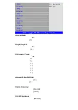


WatchDog Setting:
[Disable]
[RS485 Type]
Options: [10sec,20sec,30sec,40sec,1min,2min,4min]
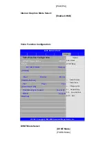
3.4.4 Hardware Health Configuration
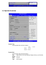
BIOS SETUP UTILITY
Advanced
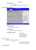
Hardware Health Configuration
Fan configuration mode
setting
← Select Screen
↑↓ Select Item
+- Charge Field F1
General Help F10
Save and Exit ESC
Exit
CPU Temperature
:41
℃
/105
℉
CPUFAN Speed
:4800 RPM
CPUFAN Mode Setting
[Manual
Mode
]
CPUFAN PWM Control
[250 ]
V02.68 © Copyright 1985-2009 American Mega trends , Inc.
CPU Temperature:
Show you the current CPU temperature.
CPUFAN Speed:
Show you the current CPU Fan operating speed.
CPUFAN Mode Setting:
[Manual Mode]
[Thermal Cruise Mode]
[Speed Cruise Mode]
[Smart Fan3 Mode]
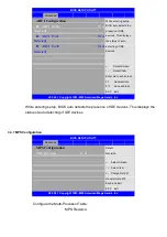
3.4.5 ACPI Configuration
Section for Advanced ACPI Configuration
Options:
[Advanced ACPI Configuration]
[Chipset ACPI Configuration]
3.4.6 AHCI Configuration
Содержание PCH3582
Страница 8: ...1 2 Dimensions Figure 1 1 Dimensions of PCH3582...
Страница 9: ...Figure 1 2 Dimensions of PCH3782...
Страница 10: ...Figure 1 3 Dimensions of PCH3982...
Страница 13: ...Figure 2 3 Jumpers and Connectors Location TOP Figure 2 4 Jumpers and Connectors Location Bottom...
Страница 33: ...1 4...
Страница 64: ...Step 5 Click Next Step 6 Click Next to continue...
Страница 68: ...Step 5 Click Install to begin the installation Step 6 Click Finish to compete the installation...
Страница 70: ...Step 3 Click Yes to continue the installation Step 4 Wait for installation...
Страница 71: ...Step 5 Select Yes I want to restart my computer now then click OK...
Страница 75: ...Step 6 Wait for installation Then click Next to continue Step 7 Click OK...
Страница 76: ...Step 8 Click Finish to compete installation...
Страница 81: ...Setting...
Страница 82: ...About This panel displays information about the PenMount controller and driver version...


