Chapter 3
81
8.
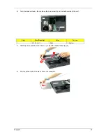
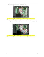
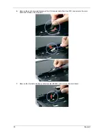
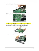
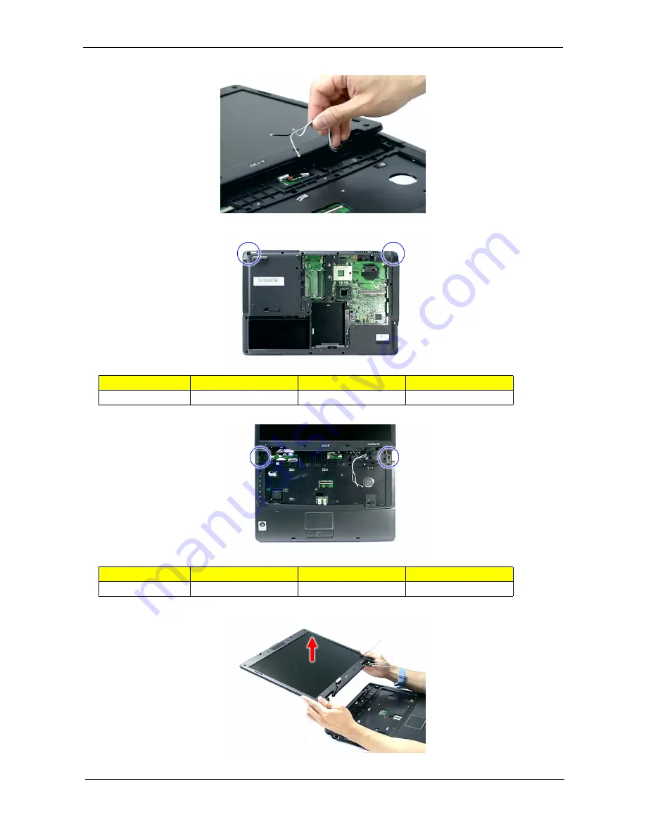
Release the wireless LAN antenna cables from the hole and latches as shown.
9.
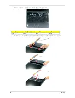
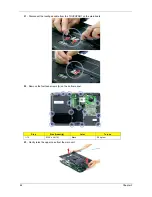
Remove the two screws (A) from the base of the unit.
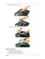
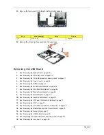
10. Remove the two screws (H) from the left and right hinge of the LCD module.
11. Carefully remove the LCD module from the base unit.
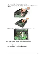
NOTE: When connecting the cable back to the unit, please note that the cable should be routed well.
Step
Size (Quantity)
Color
Torque
1~2
M2.5 x L6 (2)
Black
4.0 kgf-cm
Step
Size (Quantity)
Color
Torque
1~2
M2.5 x L8 (2)
Black
4.0 kgf-cm
Содержание Extensa 5420G
Страница 6: ...VI ...
Страница 10: ...X Table of Contents ...
Страница 65: ...Chapter 2 55 ...
Страница 66: ...56 Chapter 2 ...
Страница 111: ...Chapter 3 101 14 Remove the internal microphone from the back cover 15 Remove the Web camera from the back cover ...
Страница 112: ...102 Chapter 3 ...
Страница 126: ...116 Chapter 4 F5h Boot to Mini DOS F6h Clear Huge Segment F7h Boot to Full DOS Code Beeps ...
Страница 138: ...128 Chapter 5 ...
Страница 172: ...Appendix A 162 ...
Страница 178: ...168 Appendix C ...

