Chapter 2
25
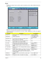
Main
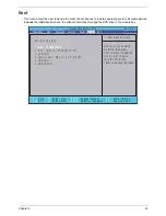
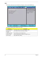
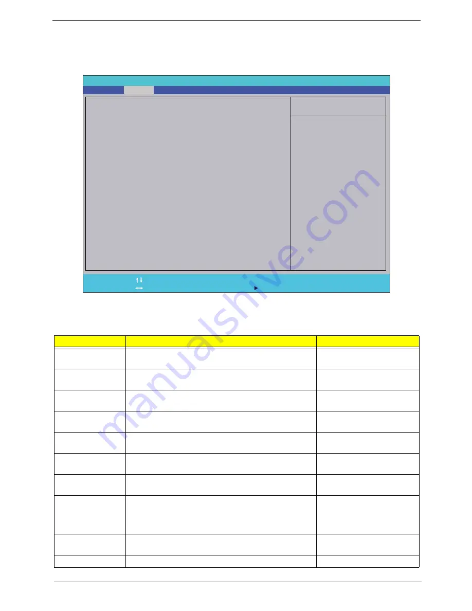
The Main screen allows the user to set the system time and date as well as enable and disable boot option
and recovery.
NOTE:
The screen above is for your reference only. Actual values may differ.
The table below describes the parameters in this screen. Settings in
boldface
are the default and suggested
parameter settings.
Parameter
Description
Format/Option
System Time
Sets the system time. The hours are displayed with 24-
hour format.
Format: HH:MM:SS
(hour:minute:second)
System Date
Sets the system date.
Format MM/DD/YYYY
(month/day/year)
System Memory
This field reports the memory size of the system.
Memory size is fixed to 2047 MB.
N/A
Video Memory
This field reports the memory allocated for video
graphics. Memory size is fixed to 64 MB.
N/A
Quick Boot
Allows startup to skip certain tests while booting,
decreasing the time needed to boot the system.
Option:
Enabled
or
Disabled
Network Boot
Enables, disables the system boot from LAN (remote
server).
Option:
Enabled
or
Disabled
F12 Boot Menu
Enable the Press <F12> to display Boot Menu message
during boot.
Option: Enabled or
Disabled
D2D Recovery
Enables, disables D2D Recovery function. The function
allows the user to create a hidden partition on hard disc
drive to store operation system and restore the system
to factory defaults.
Option:
Enabled
or
Disabled
SATA Mode
Control the mode in which the SATA controller should
operate.
Option:
AHCI
or IDE
Display Mode
Configures the mode of operation for the display
Option:
iGPU
or ?
I t e m S p e c i f i c H e l p
T h i s i s t h e h e l p f o r t h e
h o u r f i e l d . V a l i d r a n g e
i s f r o m 0 t o 2 3 .
I N C R E A S E / R E D U C E : F 5 / F 6
F 1
E S C
H e l p
E x i t
S e l e c t I t e m
S e l e c t M e n u
C h a n g e Va l u e s
S e l e c t
S u b M e n u
E n t e r
F 9
F 1 0
S e t u p D e f a u l t
S a v e a n d E x i t
[ 1 9 : 1 0 : 5 9 ]
[ 0 1 / 0 9 / 2 0 0 9 ]
4 0 9 5 M B
5 1 2 M B
[ E n a b l e d ]
[ E n a b l e d ]
[ D i s a b l e d ]
[ E n a b l e d ]
[ A H C I ]
[ i G P U ]
[ 1 9 :
1 0 : 5 9 ]
[ 0 1 / 0 9 / 2 0 0 9 ]
4 0 9 5 M B
5 1 2 M B
[ E n a b l e d ]
[ E n a b l e d ]
[ D i s a b l e d ]
[ E n a b l e d ]
[ A H C I ]
[ i G P U ]
S y s t e m T i m e :
S y s t e m D a t e :
T o t a l M e m o r y :
V i d e o M e m o r y :
Q u i c k B o o t
N e t w o r k B o o t
F 1 2 B o o t M e n u
D 2 D R e c o v e r y
S A T A M o d e
D i s p l a y M o d e
S y s t e m T i m e :
S y s t e m D a t e :
T o t a l M e m o r y :
V i d e o M e m o r y :
Q u i c k B o o t
N e t w o r k B o o t
F 1 2 B o o t M e n u
D 2 D R e c o v e r y
S A T A M o d e
D i s p l a y M o d e
F 5 / F 6
I n s y d e H 2 0 S e t u p U t i l i t y R e v . 3 . 5
Boot
Exit
Security
Information
Advanced
Power
Main
Содержание Aspire 5935 Series
Страница 6: ...VI ...
Страница 10: ...X Table of Contents ...
Страница 14: ...4 Chapter 1 System Block Diagram ...
Страница 47: ...Chapter 2 37 ...
Страница 54: ...44 Chapter 2 ...
Страница 81: ...Chapter 3 71 5 Using both hands lift the Speaker Module upward to remove it from the Upper Cover ...
Страница 83: ...Chapter 3 73 5 Disconnect the cable from the Power Saving Board as shown ...
Страница 88: ...78 Chapter 3 8 Remove the FInger Print Reader from the bracket as shown ...
Страница 98: ...88 Chapter 3 4 Lift the right side Saddle clear of the Lower Cover as shown ...
Страница 102: ...92 Chapter 3 5 Disconnect the cable from the Bluetooth Module ...
Страница 109: ...Chapter 3 99 5 Using both hands lift the Thermal Module clear of the Mainboard ...
Страница 161: ...Chapter 5 151 LS 5011P LCD Backlight Board Item Description JP1 Backlight on off Connector ...
Страница 162: ...152 Chapter 5 LS 5012P Launch Board Item Description LED1 Backup LED LED2 Bluetooth LED LED3 Wireless LED ...
Страница 164: ...154 Chapter 5 LS 5014P VR Board Item Description SW1 VR SWITCH ...
Страница 165: ...Chapter 5 155 LS 5015P Finger printer Board Item Description U2 LTT SS801U 13_LGA28 ...
Страница 170: ...160 Chapter 5 LS 501AP HDMI Board Item Description U1 CH7318A BF TR_QFN48_7X7 ...
Страница 175: ...Chapter 6 165 Base Assembly No Description Acer P N 1 HDD Memory Door 2 WLAN Door 3 Lower Cover 1 2 3 ...
Страница 183: ...Chapter 6 173 ...
Страница 212: ...Appendix A 202 ...
Страница 218: ...208 Appendix B ...
Страница 220: ...210 Appendix C ...
Страница 224: ...214 ...

