Chapter 4
145
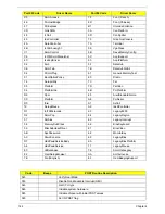
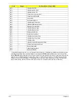
0Ah
Initialize CPU registers
0Bh
Enable CPU cache
0Ch
Initialize caches to initial POST values
0Eh
Initialize I/O component
0Fh
Initialize the local bus IDE
10h
Initialize Power Management
11h
Load alternate registers with initial POST values
12h
Restore CPU control word during warm boot
13h
Initialize PCI Bus Mastering devices
14h
Initialize keyboard controller
16h
1-2-2-3
BIOS ROM checksum
17h
Initialize cache before memory autosize
18h
8254
timer initialization
1Ah
8237
DMA controller initialization
1Ch
Reset Programmable Interrupt Controller
20h
1-3-1-1
Test DRAM refresh
22h
1-3-1-3
Test 8742 Keyboard Controller
24h
Set ES segment register to 4 GB
26h
Enable A20 line
28h
Autosize DRAM
29h
Initialize POST Memory Manager
2Ah
Clear 512 KB base RAM
2Ch
1-3-4-1
RAM failure on address line xxxx*
2Eh
1-3-4-3
RAM failure on data bits xxxx* of low byte of memory bus
2Fh
Enable cache before system BIOS shadow
30h
1-4-1-1
RAM failure on data bits xxxx* of high byte of memory bus
32h
Test CPU bus-clock frequency
33h
Initialize Phoenix Dispatch Manager
36h
Warm start shut down
38h
Shadow system BIOS ROM
3Ah
Autosize cache
3Ch
Advanced configuration of chipset registers
3Dh
Load alternate registers with CMOS values
42h
Initialize interrupt vectors
45h
POST device initialization
46h
2-1-2-3
Check ROM copyright notice
48h
Check video configuration against CMOS
49h
Initialize PCI bus and devices
4Ah
Initialize all video adapters in system
4Bh
QuietBoot start (optional)
4Ch
Shadow video BIOS ROM
4Eh
Display BIOS copyright notice
50h
Display CPU type and speed
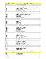
Code
Beeps
POST Routine Description
Содержание Aspire 5935 Series
Страница 6: ...VI ...
Страница 10: ...X Table of Contents ...
Страница 14: ...4 Chapter 1 System Block Diagram ...
Страница 47: ...Chapter 2 37 ...
Страница 54: ...44 Chapter 2 ...
Страница 81: ...Chapter 3 71 5 Using both hands lift the Speaker Module upward to remove it from the Upper Cover ...
Страница 83: ...Chapter 3 73 5 Disconnect the cable from the Power Saving Board as shown ...
Страница 88: ...78 Chapter 3 8 Remove the FInger Print Reader from the bracket as shown ...
Страница 98: ...88 Chapter 3 4 Lift the right side Saddle clear of the Lower Cover as shown ...
Страница 102: ...92 Chapter 3 5 Disconnect the cable from the Bluetooth Module ...
Страница 109: ...Chapter 3 99 5 Using both hands lift the Thermal Module clear of the Mainboard ...
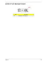
Страница 161: ...Chapter 5 151 LS 5011P LCD Backlight Board Item Description JP1 Backlight on off Connector ...
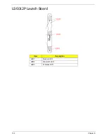
Страница 162: ...152 Chapter 5 LS 5012P Launch Board Item Description LED1 Backup LED LED2 Bluetooth LED LED3 Wireless LED ...
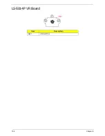
Страница 164: ...154 Chapter 5 LS 5014P VR Board Item Description SW1 VR SWITCH ...
Страница 165: ...Chapter 5 155 LS 5015P Finger printer Board Item Description U2 LTT SS801U 13_LGA28 ...
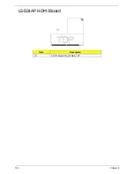
Страница 170: ...160 Chapter 5 LS 501AP HDMI Board Item Description U1 CH7318A BF TR_QFN48_7X7 ...
Страница 175: ...Chapter 6 165 Base Assembly No Description Acer P N 1 HDD Memory Door 2 WLAN Door 3 Lower Cover 1 2 3 ...
Страница 183: ...Chapter 6 173 ...
Страница 212: ...Appendix A 202 ...
Страница 218: ...208 Appendix B ...
Страница 220: ...210 Appendix C ...
Страница 224: ...214 ...

