100
Chapter 3
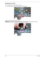
Removing the CPU
1.
See “Removing the Thermal Module” on page 98.
2.
Turn the securing screw 180° to release the CPU from the socket.
3.
Remove the CPU from the socket as shown.
IMPORTANT:
The pins on the underside of the CPU are very delicate. If they are damaged, the CPU may
malfunction. Place the CPU on a clean, dry surface when it is not installed.
Содержание Aspire 5935 Series
Страница 6: ...VI ...
Страница 10: ...X Table of Contents ...
Страница 14: ...4 Chapter 1 System Block Diagram ...
Страница 47: ...Chapter 2 37 ...
Страница 54: ...44 Chapter 2 ...
Страница 81: ...Chapter 3 71 5 Using both hands lift the Speaker Module upward to remove it from the Upper Cover ...
Страница 83: ...Chapter 3 73 5 Disconnect the cable from the Power Saving Board as shown ...
Страница 88: ...78 Chapter 3 8 Remove the FInger Print Reader from the bracket as shown ...
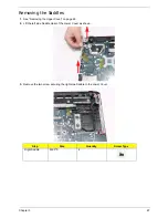
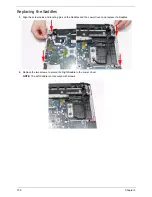
Страница 98: ...88 Chapter 3 4 Lift the right side Saddle clear of the Lower Cover as shown ...
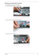
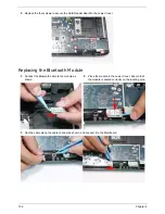
Страница 102: ...92 Chapter 3 5 Disconnect the cable from the Bluetooth Module ...
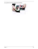
Страница 109: ...Chapter 3 99 5 Using both hands lift the Thermal Module clear of the Mainboard ...
Страница 161: ...Chapter 5 151 LS 5011P LCD Backlight Board Item Description JP1 Backlight on off Connector ...
Страница 162: ...152 Chapter 5 LS 5012P Launch Board Item Description LED1 Backup LED LED2 Bluetooth LED LED3 Wireless LED ...
Страница 164: ...154 Chapter 5 LS 5014P VR Board Item Description SW1 VR SWITCH ...
Страница 165: ...Chapter 5 155 LS 5015P Finger printer Board Item Description U2 LTT SS801U 13_LGA28 ...
Страница 170: ...160 Chapter 5 LS 501AP HDMI Board Item Description U1 CH7318A BF TR_QFN48_7X7 ...
Страница 175: ...Chapter 6 165 Base Assembly No Description Acer P N 1 HDD Memory Door 2 WLAN Door 3 Lower Cover 1 2 3 ...
Страница 183: ...Chapter 6 173 ...
Страница 212: ...Appendix A 202 ...
Страница 218: ...208 Appendix B ...
Страница 220: ...210 Appendix C ...
Страница 224: ...214 ...


