6
Chapter 1
NOTE:
1
The Power and Battery indicators are visible even when the computer cover is closed
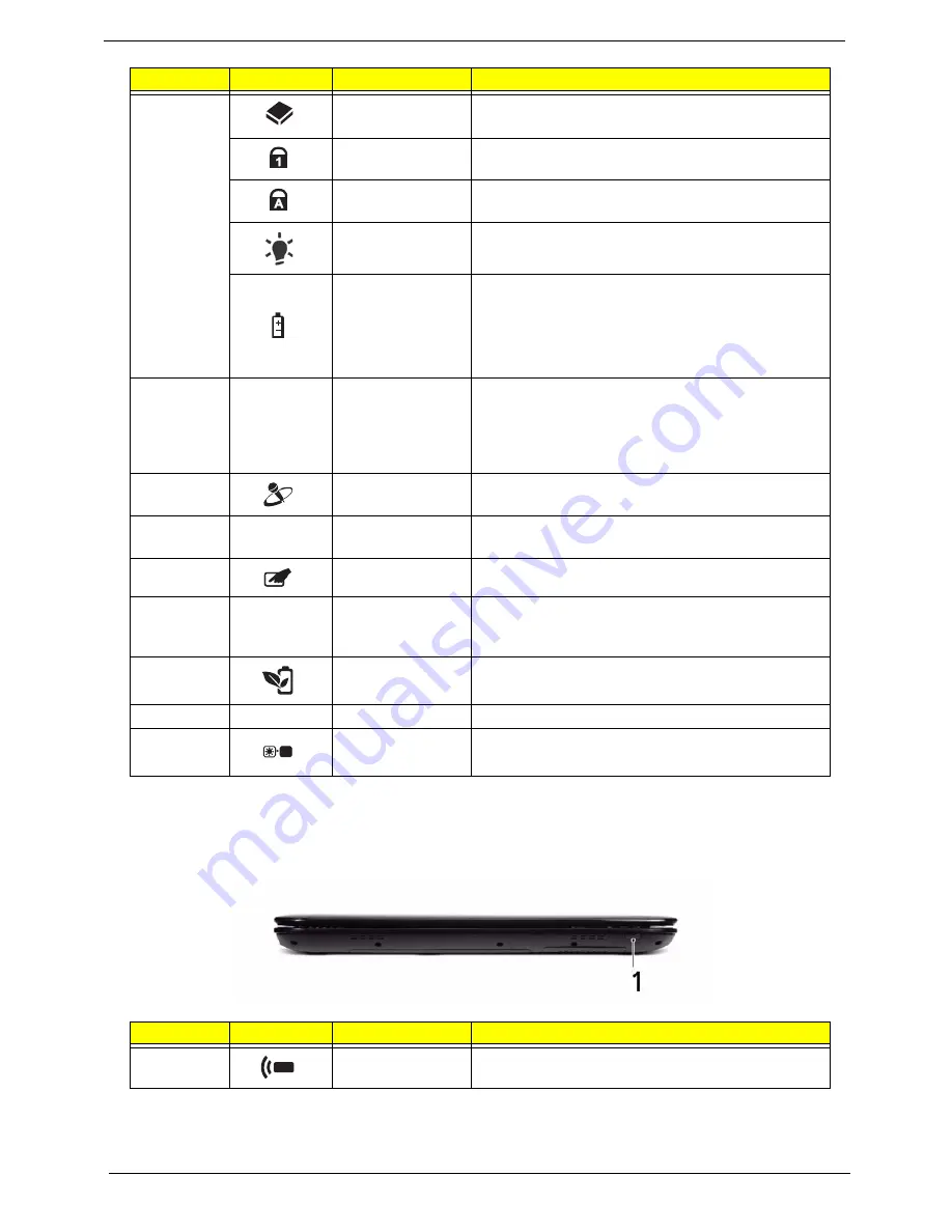
Closed Front View
7
HDD
Indicates when the hard disk drive is active.
Num Lock
Lights up when Num Lock is activated.
Caps Lock
Lights up when Caps Lock is activated.
Power
1
Indicates the computer's power status.
Battery
1
Indicates the computer's battery status.
1.
Charging: The light shows amber when the
battery is charging.
2.
Fully charged: The light shows green when in AC
mode.
8
Click buttons
(left, center* and
right)
The left and right buttons function like the left and
right mouse buttons.
*The center button serves as Acer Bio-Protection
fingerprint reader supporting Acer FingerNav 4-way
control function (only for certain models).
9
Microphone
Internal microphone for sound recording.
10
Palmrest
Comfortable support area for your hands when you
use the computer.
11
TouchPad toggle
Turns the internal TouchPad on and off.
12
Acer MediaTouch
Touch sensitive controls for Acer Arcade, volume
(up/down) and media (play/pause, stop, previous,
next); with mute and hold keys.
13
Acer PowerSmart
key
Puts your computer into power-saving mode.
14
Speakers
Left and right speakers deliver stereo audio output.
15
Screen blank
Turns the display screen backlight off to save
power. Press any key to return.
No.
Icon
Item
Description
1
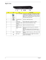
CIR receiver
Receives signals from a remote control.
No.
Icon
Item
Description
Содержание Aspire 5935 Series
Страница 6: ...VI ...
Страница 10: ...X Table of Contents ...
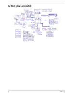
Страница 14: ...4 Chapter 1 System Block Diagram ...
Страница 47: ...Chapter 2 37 ...
Страница 54: ...44 Chapter 2 ...
Страница 81: ...Chapter 3 71 5 Using both hands lift the Speaker Module upward to remove it from the Upper Cover ...
Страница 83: ...Chapter 3 73 5 Disconnect the cable from the Power Saving Board as shown ...
Страница 88: ...78 Chapter 3 8 Remove the FInger Print Reader from the bracket as shown ...
Страница 98: ...88 Chapter 3 4 Lift the right side Saddle clear of the Lower Cover as shown ...
Страница 102: ...92 Chapter 3 5 Disconnect the cable from the Bluetooth Module ...
Страница 109: ...Chapter 3 99 5 Using both hands lift the Thermal Module clear of the Mainboard ...
Страница 161: ...Chapter 5 151 LS 5011P LCD Backlight Board Item Description JP1 Backlight on off Connector ...
Страница 162: ...152 Chapter 5 LS 5012P Launch Board Item Description LED1 Backup LED LED2 Bluetooth LED LED3 Wireless LED ...
Страница 164: ...154 Chapter 5 LS 5014P VR Board Item Description SW1 VR SWITCH ...
Страница 165: ...Chapter 5 155 LS 5015P Finger printer Board Item Description U2 LTT SS801U 13_LGA28 ...
Страница 170: ...160 Chapter 5 LS 501AP HDMI Board Item Description U1 CH7318A BF TR_QFN48_7X7 ...
Страница 175: ...Chapter 6 165 Base Assembly No Description Acer P N 1 HDD Memory Door 2 WLAN Door 3 Lower Cover 1 2 3 ...
Страница 183: ...Chapter 6 173 ...
Страница 212: ...Appendix A 202 ...
Страница 218: ...208 Appendix B ...
Страница 220: ...210 Appendix C ...
Страница 224: ...214 ...


